EasyManua.ls Logo

Kenwood KDC-MP5539U User Manual

Kenwood KDC-MP5539U
48 pages
To Next Page IconTo Next Page
Page #1 background imageLoading...
Page #1 background image
This product uses Lead Free solder.
This product complies with the
RoHS directive for the European market.
© 2008-2 PRINTED IN JA PAN
B53-0614-00
(
N
)
519
KDC-MP408U/MP438U/X492
KDC-MP5039U/MP5539U
KDC-W5041UA/W5041UG
KDC-W5141UAY/W5141UGY
KDC-W5541U/W5641UY
SERVICE MANUAL
CD RECEIVER
TDF SPARE-PANEL
MAIN UNIT NAME TDF PARTS No. TDF NAME
KDC-MP408U Y33-2920-62 TDF-MP84DT
KDC-MP438U Y33-2920-61 TDF-MP84D
KDC-MP5039U Y33-2920-64 TDF-MP5039U
KDC-MP5539U Y33-2920-63 TDF-MP5539U
KDC-W5041UA Y33-2920-66 TDF-W5041UA
KDC-W5041UG Y33-2920-67 TDF-W5041UG
KDC-W5141UAY Y33-2920-66 TDF-W5041UA
KDC-W5141UGY Y33-2920-67 TDF-W5041UG
KDC-W5541U Y33-2920-65 TDF-W5541U
KDC-X492
KDC-MP438U
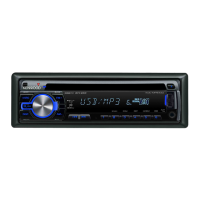
KDC-MP408U
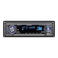
KDC-MP5539U
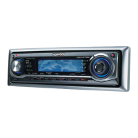
KDC-MP5039U
KDC-W5041U
KDC-W5641U
KDC-W5141U
KDC-W5541U
KDC-W5641UY Y33-2920-65 TDF-W5541U
KDC-X492 Y33-2920-60 TDF-84DX
Mounting hardware assy
(J21-9716-03)
Lever
(D10-7012-04) x2
* DC cord
(E30-6428-05)
* Screw set
(N99-1757-15)
* Escutcheon
(B07-xxxx-xx)
* Carrying case
(W01-xxxx-xx)
* DC cord
(E30-6671-05)
* Screw (4x16)
(N84-4016-48)
* Plastic cabinet assy
(A02-2755-13)
* Remote controller assy (RC-547)
(A70-2085-05)
Battery
(Not supplied)
* Depends on the model. Refer to the parts list.
KDC-MP408U : Panel assy (A64-4400-02)
KDC-MP5039U : Panel assy (A64-4402-02)
KDC-W5041Ux : Panel assy (A64-4404-02)
KDC-W5541U : Panel assy (A64-4403-02)
KDC-X492 : Panel assy (A64-4398-02)
KDC-MP438U : Panel assy (A64-4399-02)
KDC-MP5539U : Panel assy (A64-4401-02)
KDC-W5141Uxx : Panel assy (A64-4406-02)
KDC-W5641UY : Panel assy (A64-4405-02)
Question and Answer IconNeed help?

Do you have a question about the Kenwood KDC-MP5539U and is the answer not in the manual?

Kenwood KDC-MP5539U Specifications

General IconGeneral
BrandKenwood
ModelKDC-MP5539U
CategoryCar Receiver
LanguageEnglish

Summary

Block Diagram and Components

Block Diagram

Visual representation of the system's electrical connections and signal flow.

Components Description

Detailed list and function of electrical components used in the unit.

Microcomputer Terminal Description

System µ-COM IC600 Terminal Description

Pin assignment and function for the main microcomputer.

Test Mode Operations

Test Mode Entry, Clearing, and Defaults

Procedures for accessing, exiting, and understanding default settings in test mode.

Specific Test Mode Procedures

Operations for tuner, CD, audio, security, and ROM transfer test modes.

ROM Data Transfer Processes

Overview and Specifications

Explanation of ROM data transfer function and its specifications.

Operation Procedure

Step-by-step guide for transferring ROM data between units.

PC Board Layouts

Switch Unit PC Boards

Component and foil side views of the switch unit circuit board.

Electric Unit PC Boards

Component and foil side views of the electric unit circuit board.

CD Player Unit PC Boards

Component and foil side views of the CD player unit circuit board.

Exploded Views

CD Mechanism Exploded View

Diagram showing the assembly of the CD mechanism components.

Unit Exploded View

Diagram showing the assembly of the main unit components.

Parts List

Electric Unit Parts List

List of all replaceable parts for the electric unit.

Mechanism and Switch Unit Parts

List of parts for the CD mechanism and switch unit.

CD Player Unit Parts List

List of all replaceable parts for the CD player unit.

Specifications

Model "K" Specifications

Technical details for models designated as "K".

Model "M" Specifications

Technical details for models designated as "M".

Model "E" Specifications

Technical details for models designated as "E".

Related product manuals