B5A-2894-00 (M)
© 2019
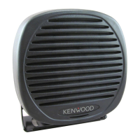
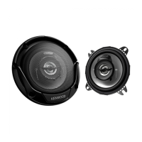
KES-5A KES-5A KES-5A
EXTERNAL SPEAKER
INSTRUCTION MANUAL
Note: The following instructions are for use by your KENWOOD dealer, an
authorized KENWOOD service facility, or the factory.
SPECIFICATIONS
Rated Input Power............................................................................ 20 W
Maximum Input Power ..................................................................... 40 W
Impedance ..........................................................................................4
Dimensions (W x H x D)............................................ 129 x 129 x 77 mm
(5.08 x 5.08 x 3.03 inches)
Weight .............................................................................. 840 g (29.6 oz)
SUPPLIED ACCESSORIES
a
Mounting bracket (J2K-0242-XX) ...................................................... 1
b
Mounting screw A (N0Y-0030-XX) .................................................... 2
Screw set (N9X-0053-XX)
c
Self-tapping screw ......................................................................... 4
d
Hex-headed bolt ............................................................................ 4
e
Spring washer................................................................................ 4
f
Flat washer .................................................................................... 4
g
Flange nut ...................................................................................... 4
h
Mounting screw
B
.......................................................................... 2
Instruction manual .................................................................................. 1
TOOLS REQUIRED
The following tools are required for installing
the external speaker:
• 6 mm or larger electric drill
• 6 mm drill bit for the hex-headed bolts
• 4.2 mm drill bit for the self-tapping screws
INSTALLING THE EXTERNAL SPEAKER
1 Attach the mounting bracket to the vehicle
dash or other secure location using the self-
tapping screws or the hex-headed bolts with
the fl ange nuts and washers.
• The bracket can be attached upright,
reversed, or even fl at against its back
through the provided mounting holes.
2 Attach the speaker to the mounting bracket
using the mounting screws.
• You can use either mounting screws A or
mounting screws B. Mounting screws B
allow for greater security, as they can be
tightened more than mounting screws A.
HAUT PARLEUR EXTERNE
MODE D’EMPLOI
Remarque : Les instructions suivantes sont à l’intention de votre revendeur
KENWOOD, d’un centre de service autorisé KENWOOD ou de l’usine.
FICHE TECHNIQUE
Puissance d’entrée nominale ........................................................... 20 W
Puissance d’entrée maximale .......................................................... 40 W
Impédance ..........................................................................................4
Dimensions (L x H x P) ............................................. 129 x 129 x 77 mm
Poids.................................................................................................840 g
ACCESSOIRES FOURNIS
a
Support de mongage (J2K-0242-XX) ............................................... 1
b
Vis de montage A (N0Y-0030-XX) ..................................................... 2
Jeu de vis (N9X-0053-XX)
c
Vis taraudeuses ............................................................................. 4
d
Boulon à tête hexagonale .............................................................. 4
e
Rondelle à ressort ......................................................................... 4
f
Rondelle ordinaires ....................................................................... 4
g
Écrou à six pans ............................................................................ 4
h
Vis de montage B .......................................................................... 2
Mode d’emploi ........................................................................................ 1
OUTILS REQUIS
Vous avez besoin des outils suivants pour
l’installation du haut parleur externe:
• perceuse électrique de 6 mm ou plus
• mèche de 6 mm pour les boulons à tête
hexagonale
• mèche de 4,2 mm pour les vis taraudeuses
INSTALLATION DU HAUT PARLEUR
EXTERNE
1 Fixez le support de montage sur le tableau
de bord du véhicule ou à un autre endroit
solide à l’aide des vis taraudeuses ou des
boulons à tête hexagonale avec écrous à
six pans et rondelles.
• Le support peut être fi xé à l’endroit, à
l’envers ou même à plat contre sa face
arrière en utilisant les trous de montage
prévus à cet effet.
2 Fixez le haut parleur au support de montage
à l’aide des vis de montage.
• Vous pouvez utiliser les vis de montage
A ou les vis de montage B. Les vis
de montage B sont plus sécuritaires
puisqu’elles peuvent être serrées
davantage que les vis A.
ALTAVOZ EXTERNO
MANUAL DE INSTRUCCIONES
Nota: Las siguientes instrucciones son para su proveedor KENWOOD, un centro
de reparaciones autorizado KENWOOD, o la fábrica.
ESPECIFICACIONES
Potencia de entrada nominal ........................................................... 20 W
Potencia de entrada máxima ........................................................... 40 W
Impedancia ..........................................................................................4
Dimensiones (A x A x P) ........................................... 129 x 129 x 77 mm
Peso .................................................................................................840 g
ACCESORIOS SUMINISTRADOS
a
Soporte de montaje (J2K-0242-XX) .................................................. 1
b
Tornillo de montaje A (N0Y-0030-XX) ............................................... 2
Juego de tornillos (N9X-0053-XX)
c
Tornillo de rosca cortante .............................................................. 4
d
Perno de cabeza hexagonal .......................................................... 4
e
Arandela elástica ........................................................................... 4
f
Arandela plana .............................................................................. 4
g
Tuerca con resalto ......................................................................... 4
h
Tornillo de montaje
B
..................................................................... 2
Manual de instrucciones ........................................................................ 1
HERRAMIENTAS NECESARIAS
Las siguientes herramientas son necesarias
para instalar el altavoz externo:
• Taladro eléctrico de 6 mm ó más
• Barrena de 6 mm para los pernos de
cabeza hexagonal
• Barrena de 4,2 mm para los tornillos de
rosca cortante
INSTALACIÓN DEL ALTAVOZ EXTERNO
1 Asegure el soporte de montaje al tablero
del vehículo o a otro sitio seguro utilizando
los tornillos de rosca cortante o los pernos
de cabeza hexagonal con las tuercas con
resalto y las arandelas.
• El soporte se puede acoplar al derecho,
al revés o hasta plano contra su parte
posterior con los agujeros de montaje
provistos.
2 Acople el altavoz al soporte de montaje
utilizando los tornillos de montaje.
• Se pueden utilizar los tornillos de montaje
A o B. Los tornillos de montaje B son más
seguros, ya que se pueden ajustar más
que los tornillos A.