Do you have a question about the Kenwood KM330 and is the answer not in the manual?
Steps to remove the high speed and slow speed outlet covers.
Importance of noting the spigot's position for attachment fitting.
Procedure for removing the plastic washer and drive belt.
Method to remove the gearbox pulley using a stall plug in the slow speed outlet.
Method to remove the gearbox pulley using a mincer attachment.
Procedure to remove the hub nut secured by adhesive.
Tips for removing a difficult hub nut by tapping the shaft.
Apply grease sparingly to the planet gear for transfer to the ring gear.
Apply threadlock 60026 to the hub nut before re-assembly.
Steps to prepare for regreasing by removing the slow speed lever knob and cover.
Remove the red plug and re-grease the gearbox while the appliance runs at low speed.
Procedure to remove the three motor retaining screws and cams.
Warning against overtightening motor retaining screws to prevent loosening.
Refit covers to create a stand and protect casing before turning the appliance upside down.
Loosen cord grip screws and pull the mains lead through the casing.
Remove bracket, operate lever, and slide quadrant into pedestal.
Lift out the motor assembly, control module, and body cover from the main housing.
Move body cover, expose hinge pin, and remove the circlip to detach the pedestal.
Slide out the hinge pin, using a screwdriver if needed, to complete pedestal removal.
Ensure body cover is correctly located under the hinge pin during re-assembly.
Correctly position the head lift cam and spring, fitting the flat edge against the pedestal.
Insert feet flush with the pedestal and lock the pin into position with a punch and mallet.
Check the head lift lever knob hangs vertically when the machine is closed.
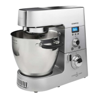
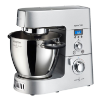
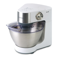
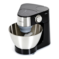
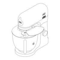
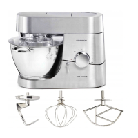
This document outlines the disassembly and re-assembly procedures for the Kenwood KM330 series Chef and KM630 series Major (Pinto) kitchen machines, providing detailed instructions for service and repair.
Before undertaking any maintenance or repair, it is crucial to disconnect the appliance from the mains supply to prevent electrical hazards. Additionally, care should be taken to protect the finish on the casings during removal and handling of parts. The instructions are supplemented with images, which can be clicked to view larger versions for better clarity.
To access the internal gearbox components, the high-speed outlet cover must first be removed. This is achieved by pulling back the slow-speed lever to unlock it, then detaching the slow-speed outlet cover. The document highlights the importance of noting the correct position of the spigot before removal, as its alignment dictates the proper positioning of attachments when fitted. Following this, the top cover of the appliance can be removed to expose more internal components.
Once the top cover is off, a plastic washer and the drive belt need to be removed. Dismantling the gearbox further involves the removal of the large pulley, which can be a tight fit on the pinion shaft. Two methods are suggested to facilitate this:
After loosening, two screwdrivers may be required to prise the pulley off the pinion shaft due to its tight fit. Re-assembly of the pulley involves using either the stall plug or mincer method, turning the pulley clockwise to tighten it.
The hub nut, which secures the planet hub assembly, is often held in place by an engineering adhesive, making its removal potentially challenging. An 8mm socket is recommended for this task. A tool should be positioned between the hub spout and the hub nut, as shown in the diagrams, taking care not to damage the appliance's finish. The nut is removed by turning it anti-clockwise.
If the hub proves particularly difficult to remove, a specific technique is advised: stand the appliance upright and gently tap the end of the screw (vertical drive shaft) with a mallet, while simultaneously pulling down on the hub spout. For re-assembly, it is important to apply threadlock 60026 to the hub nut before tightening it. When re-assembling the planet gear, grease should be applied sparingly to the planet gear itself, as this grease will transfer to the ring gear during operation.
For regreasing the gearbox, the machine should be turned upside down. The slow-speed lever knob needs to be removed, followed by undoing the two gearbox cover screws and removing the cover. Once the cover is off, a red plug can be removed, and the gearbox re-greased. It is recommended to run the appliance on its lowest speed setting during this process to distribute the grease effectively. The document notes that a special food-grade grease is a stock item and should be used for this purpose.
To access and remove the motor and control module, all top covers must first be removed as detailed in the preceding steps. Subsequently, the three motor retaining screws and cams need to be removed. A critical note is provided regarding these screws: they should never be overtightened, as this can lead to them eventually working loose.
After removing the motor and control module, the top cover and liquidiser outlet cover should be loosely refitted. These covers then serve as a stand for the appliance. The machine should be turned upside down, using a mat to protect the casing from damage.
With the appliance inverted, the two cord grip screws can be loosened, allowing the mains lead to be pulled through as shown in the illustrations.
To proceed with disassembling the head lift mechanism, the head lift lever must be operated. While doing so, the pedestal should be restrained, allowing the machine to open slowly. The two screws securing the quadrant bracket are then removed. After removing the bracket and its screws, the head lift lever is operated again, and the quadrant is slid into the pedestal.
At this stage, the motor assembly, control module, and body cover can be carefully lifted out of the main body of the appliance.
The date code of the appliance can be found on the flat face of the motor housing. The document clarifies that only the four upper characters of the code represent the date. For example, a code like "6M42" translates to "2006-October-week 42." Further details on product date codes are available via a provided link.
The control module can then be dismantled as needed for repair or replacement.
To remove the pedestal, the machine should again be placed upside down, with the quadrant screws already removed. The body cover needs to be moved out of its usual position to expose the hinge pin. A circlip securing the hinge pin is then removed. The hinge pin can then be slid out, using a screwdriver if necessary. Once the hinge pin is removed, the pedestal can be detached.
Re-assembly is performed in reverse order of disassembly. It is important to ensure that the body cover correctly locates under the hinge pin at both ends. A specific note is made regarding the correct positioning of the head lift cam and spring: the flat edge of the cam should be fitted against the pedestal, as illustrated.
The document provides instructions for correctly fitting the appliance feet. Each foot should be inserted so that it is fully flush with the pedestal. After insertion, a pin punch and mallet are used to lock the pin into position, securing the foot.
When the machine is closed, the lever knob of the head lift mechanism should hang vertically. To open the machine, the lever should be swung back and up.
This comprehensive guide ensures that users and technicians can safely and effectively disassemble, maintain, and re-assemble the Kenwood KM330 series Chef and KM630 series Major kitchen machines.
| Bowl Capacity | 4.3 L |
|---|---|
| Weight | 4.5 kg |
| Bowl Material | Stainless Steel |
| Pulse Function | Yes |
| Material | Plastic and Metal |
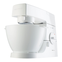
| Color | White |
| Speeds | 6 |