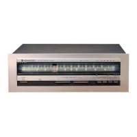
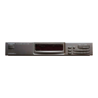
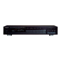
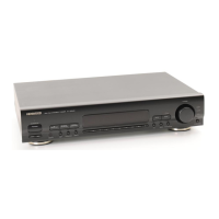
The Kenwood KT-1100D is a Quartz Synthesizer AM-FM Stereo Tuner, designed for high-fidelity audio reception.
Function Description
The KT-1100D is engineered to provide clear and precise reception of both AM and FM stereo broadcasts. Its core functionality revolves around a Quartz Synthesizer for stable tuning, ensuring that selected frequencies are held accurately. The tuner incorporates a Direct Pure MPX system, which enables stereo decoding without beat interference by linearly multiplying two analog signals: the stereo composite signal and a 38 kHz sine wave subcarrier signal. This design aims for a high signal-to-noise ratio and resistance to overmodulation.
The device features a digital rotary tuning mechanism. This system uses transparent slits on a rotating disk, attached to the tuning knob, which pass through a photo-interrupter (PH1). PH1, comprising an LED, phototransistor, and logic circuits, identifies the rotary direction and generates pulses proportional to the number of slits. These signals are processed by logic circuits (IC7 and IC8) to generate UP and DOWN pulses, controlling the tuning speed and direction. IC7 distributes pulses for UP/DOWN directions, while IC8 prevents malfunctions and acts as a frequency divider and monostable multivibrator.
The tuner includes an auto-stop signal generator circuit for both FM and AM modes. In FM mode, when no signal is input (detune), the range mute signal is high (5V), causing IC1 to output -15V. If a weak signal is input, the range mute signal becomes low (1V or less), and IC1 outputs +15V, but the S-meter voltage remains low, keeping IC1 at -15V. When a strong broadcast station is received, the range mute signal is 0V, and IC1 outputs +15V as the S-meter voltage is high. In AM mode, an AM+B signal is applied to IC1, fixing its output at +15V regardless of the range mute signal. A stop signal is generated when the AM S-meter voltage rises above 1V.
A two-stage power ON/OFF muting circuit is implemented. Upon power-on, INH, display, and audio muting signals are sequentially generated by IC15. The audio muting voltage is derived from the output voltage of an op-amp (IC2). This ensures that audio muting is activated when IC2's output exceeds 3V, preventing unwanted noise during power transitions.
The muting circuit on switching operates when any of the DIS/DIR, WID/NAR keys are pressed. This action inverts the voltage to a low level, causing IC16 to go high and charge C145, which then generates the muting signal. In REC CAL mode, IC16 is forcibly held high by D54, preventing muting signal generation during switch operations.
Important Technical Specifications
FM Tuner Section (EIA)
- Usable Sensitivity: 10.8 dBf (0.95 µV) in DISTANCE mode, 31.2 dBf (10 µV) in DIRECT mode.
- 50dB Quieting Sensitivity:
- Mono: 16.2 dBf (1.8 µV)
- Stereo: 38.8 dBf (24 µV)
- Signal to Noise Ratio (85 dBf):
- Mono: 92 dB
- Stereo: 86 dB
- Total Harmonic Distortion (WIDE/NARROW):
- Mono (100 Hz): 0.009% / 0.05%
- Mono (1,000 Hz): 0.005% / 0.04%
- Mono (50 Hz~10,000 Hz): 0.015% / 0.1%
- Stereo (100 Hz): 0.02% / 0.3%
- Stereo (1,000 Hz): 0.008% / 0.06%
- Stereo (50 Hz~10,000 Hz): 0.05% / 0.3%
- Capture Ratio: 1.0 dB (DISTANCE), 2.5 dB (DIRECT)
- Alternate Channel Selectivity (±400 kHz): 70 dB (WIDE), 100 dB (NARROW)
- Stereo Separation:
- 1,000 Hz: 70 dB / 55 dB
- 50 Hz~10,000 Hz: 50 dB / 45 dB
- 15,000 Hz: 45 dB / 40 dB
- Frequency Response: 20 Hz to 15 kHz (+0.5 dB, -0.5 dB)
- Spurious Rejection Ratio: 100 dB
- Image Rejection Ratio: 80 dB
- IF Rejection Ratio: 110 dB
- AM Suppression Ratio: 70 dB
- Subcarrier Suppression Ratio: 70 dB
- Antenna Impedance: 75 ohms unbalanced
- Tuning Frequency Range: 87.5 MHz to 108 MHz
- Output Level (1 kHz, 100% dev. Fixed): 0.6V / 1.7 kΩ
AM Tuner Section
- Usable Sensitivity: 10 µV (250 µV/m)
- S/N Ratio (1 mV input): 52 dB
- Image Rejection Ratio: 40 dB
- Total Harmonic Distortion: 0.4% (WIDE), 0.6% (NARROW)
- Selectivity: 25 dB (WIDE), 50 dB (NARROW)
General
- Power Consumption: 18 W
- Dimensions (W x H x D): 440 mm (17-5/16") x 88 mm (3-15/32") x 331 mm (13-1/16")
- Weight (Net): 4.6 kg (10.2 lb)
Usage Features
The KT-1100D offers several user-selectable modes and controls:
- DIRECT/DISTANCE Select Control (Q49): Receives signals from IC17 (pin 10) to turn DISTANCE mode ON, outputting 5V.
- WIDE/NARROW Select Control (Q50): Receives signals from IC17 (pin 3) and outputs 5V when in WIDE mode.
- AUTO/MANUAL Select (Q61): Sends latch output to the controller and LED (AUTO).
- REC CAL ON/OFF Select (Q62): Sends latch output to LED and control circuit when REC CAL is ON.
- Program Control (Q55): Transmits signals to the M81 controller.
- P-CH A/B Select (Q59): Sends latch output to display LED (CH A LED driver) and to the controller to change channels.
- Tuning Knob: Allows for precise manual tuning.
- Display: Features an FL display for frequency and other status indicators.
Maintenance Features
The manual provides detailed instructions for disassembly and adjustment, crucial for maintenance and repair:
Disassembly for Repair:
- Remove 6 screws from the metallic cabinet.
- Remove the metallic cabinet by sliding it in the direction of the arrow.
- Loosen the set screw on the knob and remove the knob from the front panel.
- Remove 5 screws from the front panel.
- Remove the front panel by sliding it in the direction of the arrow.
- Remove 2 push rivets and a screw retaining the escutcheon.
- Remove 4 screws from the sub-panel (2 front, 2 lower).
- Remove 2 screws at the sub-panel on the bottom plate.
- Pull the sub-panel slightly forward.
- Remove 2 screws from the Quieting control unit.
- Remove the screw on the Sub-unit (X13-5422-72) (D/5) and then remove the Sub-unit (X13-) (D/5).
- Remove 3 push rivets retaining the Sub-unit (X13-) (A/5) to the sub-panel.
- Remove the Sub-unit (X13-) (A/5) by sliding it in the direction of the arrow.
- Loosen 2 screws at the rear side of the bottom plate.
- Remove 2 screws at the front side on the bottom plate.
- When removing only the bottom plate, also remove 2 screws from the front side.
- Remove the bottom plate.
- Remove 7 screws retaining the right frame (4 on the tuner unit, 2 on the rear panel, and 1 from the frame at the bottom of the board).
- Pull out the right frame slightly forward and remove it.
Adjustment:
The manual outlines a comprehensive adjustment procedure for both FM and AM sections, including:
- IFT Adjustment: Connect a genescope to C19 and L8 (FM) or pin 13 of IC4/R98/C61 (AM) for maximum amplitude and symmetry.
- Band Edge Adjustment: Connect a DC voltmeter between TP6 and TP7, tuning to specific frequencies (87.5MHz/108.0MHz for FM, 531kHz/1602kHz for AM) to achieve specified voltage outputs.
- Discriminator/PLL Detector Adjustment: Connect a DC voltmeter between TP10/TP11 (discriminator) or TP12/TP13 (PLL detector) to achieve 0.000V±10mV.
- RF Alignment: Connect a genescope to specific points to maximize amplitude and symmetry.
- Auto-Stop Sensitivity Adjustment: Tune to 98.0MHz, input 1kHz, ±75kHz dev, 12dBu (ANT input), and turn VR1 clockwise until the Modulation indicator lights.
- MPX VCO Adjustment: Connect a frequency counter between TP14 and GND to adjust VR4 for 19.000kHz±15Hz.
- Sub Carrier (38kHz) Adjustment: Input 100Hz, ±68.25kHz dev, Pilot: ±6.75kHz dev, 80dBu (ANT input), and adjust L25 for minimum distortion.
- Distortion Adjustments (DET, MONO, STEREO): Input specific signals and adjust VR3, VR4, VR6, VR5, VR7 for minimum distortion.
- Separation Adjustments (R-L, L-R, NARROW L-R): Input specific signals and adjust VR2, VR3, VR1 for minimum crosstalk.
- T-S Meter Adjustment: Tune to 98.0MHz, input 10Hz, ±100kHz dev, 80dBu (ANT input), and adjust VR2 so that the red colors at the extremities of the center light uniformly.
- Deviation Adjustment: With REC CAL ON, adjust VR4 to position where the 4th dot lights.
- Signal Meter Adjustment: Tune to 98.0MHz, input 1kHz, ±75kHz dev, 40dBu (ANT input), and adjust VR3 for lighting of the 7th dot.
The manual also notes that specifications may change due to continuous advancements in development and that component and circuitry modifications may occur to ensure optimal operation under differing local conditions. It emphasizes the use of alternate schematic diagrams and parts lists for regional circuit modifications.