Do you have a question about the Kenwood KT-413 and is the answer not in the manual?
Explains how the motor operates, including driving power.
Details initial logic states of control ICs after power-on.
Describes motor operation for rightward movement and state changes.
Explains how the motor direction is reversed.
Details how the stop signal is generated to halt the motor.
Details how input signal levels are used to detect stop conditions.
Explains the detection of accurate tuning signals.
Describes how stop signals are generated.
Explains the lock signal mechanism for tuning accuracy.
Discusses FM detection and T-meter functionality.
Explains AM detection and local oscillator frequency characteristics.
Describes how the unit handles preset tuning operations.
Explains the stereo LED lighting mechanism.
Details how the lock LED lights up.
Describes the +B switch for LED and muting release.
Explains the operation of Q17 and its effect on motor and muting.
Details the operation of the muting sub unit at FM low.
Setting the initial voltage for FM presets.
Tuning the center frequency for FM.
Second part of FM tuning center adjustment.
Automatic Frequency Control adjustment for FM.
Adjustment of the FM noise amplifier.
Setting the FM signal strength indicator LEDs.
FM tracking adjustment (part 1).
FM tracking adjustment (part 2).
Adjusting FM distortion factor.
Confirming FM stop level (low setting).
Confirming FM stop level (high setting).
Adjusting the FM Voltage Controlled Oscillator.
Adjusting FM stereo separation.
FM Intermediate Frequency Transformer adjustment.
Setting the initial voltage for AM presets.
AM tracking adjustment (part 1).
AM tracking adjustment (part 2).
Automatic Frequency Control adjustment for AM.
Adjustment of the AM noise amplifier.
AM beat adjustment for maximum sensitivity.
Adjustment of the AM 9kHz filter.
AM Intermediate Frequency Transformer adjustment (part 1).
AM Intermediate Frequency Transformer adjustment (part 2).
AM Intermediate Frequency Transformer adjustment (part 3).
Lists semiconductor part numbers and their suitable replacements.
Diagram of the front end PC board with component layout.
Diagram of the main tuner PC board with component layout.
| Tuning Bands | FM, MW |
|---|---|
| Tuning Scale | Analog |
| Signal to Noise Ratio (FM) | 70 dB |
| Signal-to-Noise Ratio (FM) | 70 dB |
| Signal to Noise Ratio (MW) | 50 dB |
| Frequency Response (FM) | 30 - 15000 Hz |
| Dimensions | 430 x 280 x 100 mm |
| Weight | 3.5 kg |
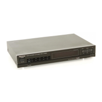
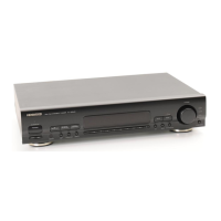
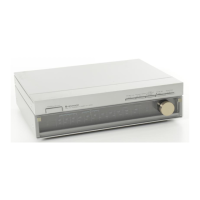
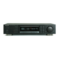
| Type | Stereo Tuner |
| FM Tuning Range | 87.5 - 108.0 MHz |
| MW Tuning Range | 530 - 1605 kHz |
| AM Tuning Range | 530 - 1605 kHz |
| Sensitivity (FM, IHF) | 1.0 µV |
| Sensitivity (MW) | 25 µV |
| Total Harmonic Distortion (FM) | 0.5% |
| Power Supply | 220V |
| Signal-to-Noise Ratio (AM) | 50dB (MW) |