Do you have a question about the Kenwood KT-615 and is the answer not in the manual?
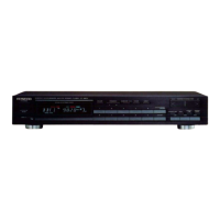
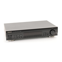
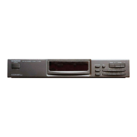
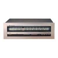
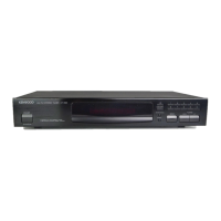
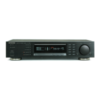
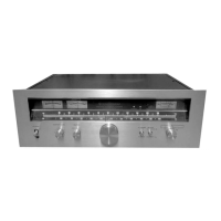
Identifies front panel controls, meters, and connectors.
Identifies rear panel connectors, switches, and power cord.
Shows the internal layout of components and the tuner PC board.
Step-by-step instructions for routing the dial cord.
Illustrates the signal flow and functional blocks of the tuner.
Lists parts with their numbers, descriptions, and locations in the exploded view.
Visual representation of the unit's components and their assembly.
Details specific screws and hardware used for assembly.
Detailed listing of capacitors, resistors, semiconductors, and other parts.
Continuation of detailed listings for key components.
Lists variable components, coils, inductors, filters, and switches.
Procedures for aligning FM tuning and detection circuits.
Procedures for aligning AM tuning circuits.
Provides important notes and definitions for adjustment procedures.
Adjustment procedures for the FM section in French.
Adjustment procedures for the AM section in French.
Important notes and definitions for adjustments in French.
Adjustment procedures for the FM reception section in German.
Adjustment procedures for the AM reception section in German.
Notes and definitions for adjustment procedures in German.
Diagram showing test equipment connections for adjustments.
Lists alternative semiconductor parts for replacement.
Component placement on the main printed circuit board.
Details on circuit modifications for different regions.
Technical specifications for the FM tuner section.
Technical specifications for the AM tuner section.
Overall technical specifications of the unit.
Complete circuit diagram of the tuner.
Displays measured waveforms for various FM signals.
Displays measured waveforms for AM signals.
Displays measured waveforms for various FM and AM signals.
Lists Kenwood and Trio-Kenwood Corporation addresses.
| Tuning Bands | FM, MW |
|---|---|
| Tuning Scale | Analog |
| FM Tuning Range | 88 to 108 MHz |
| MW Tuning Range | 530 to 1600 kHz |
| Sensitivity (FM) | 1.9 µV (IHF) |
| Selectivity (FM) | 60 dB |
| Signal to Noise Ratio (FM) | 70 dB |
| Signal to Noise Ratio (AM/MW) | 50 dB |
| Distortion (FM) | 0.3% |
| Frequency Response (FM) | 30 Hz to 15 kHz |
| Output Voltage | 750mV |
| Power Supply | AC 220 - 240 V, 50/60 Hz |
| Type | Stereo FM/AM Tuner |
| AM Tuning Range | 530 to 1600 kHz |