EasyManua.ls Logo

Kenwood M) User Manual

Kenwood M)
42 pages
To Next Page IconTo Next Page
Page #1 background imageLoading...
Page #1 background image
VHF FM TRANSCEIVER
TK-2160
© 2003-8 PRINTED IN JAPAN
B51-8652-00 (S) 1214
SERVICE MANUAL
Knob (CH-SELECTOR)
(K29-9280-13)
Knob (VOLUME)
(K29-9278-13)
Cabinet assy
(A02-3826-33)
Knob (PTT)
(K29-9279-03)
Antenna
(KRA-26: Option)
GENERAL .............................................................2
SYSTEM SET-UP .................................................2
OPERATING FEATURES .....................................3
REALIGNMENT....................................................4
DISASSEMBLY FOR REPAIR ..............................5
CIRCUIT DESCRIPTION .......................................7
INSTALLATION..................................................11
TERMINAL FUNCTION......................................12
SEMICONDUCTOR DATA .................................13
COMPONENTS DESCRIPTION .........................14
PARTS LIST........................................................15
EXPLODED VIEW...............................................23
PACKING ............................................................24
ADJUSTMENT ...................................................25
PC BOARD
TX-RX UNIT (X57-672X-XX) ........................30
SCHEMATIC DIAGRAM.....................................34
BLOCK DIAGRAM..............................................38
LEVEL DIAGRAM...............................................40
KSC-30................................................................41
SPECIFICATIONS............................BACK COVER
CONTENTS
Does not come with antenna.
Antenna is available as an option.
Question and Answer IconNeed help?

Do you have a question about the Kenwood M) and is the answer not in the manual?

Kenwood M) Specifications

General IconGeneral
BrandKenwood
ModelM)
CategoryTransceiver
LanguageEnglish

Summary

General / System Setup

Manual Introduction and Parts Ordering

Details on manual scope, intended audience, and ordering replacement parts.

Important Personal Safety Precautions

Essential safety guidelines for operating and servicing the transceiver.

Service and Maintenance Overview

Information on the radio's design for easy servicing and reference to diagrams.

Operating Features

Transceiver Installation Guide

Instructions for installing optional antenna, belt clip, and covers.

Transceiver Controls and Indicators

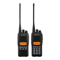
Description of front panel controls like LED, channel switch, PTT, and keys.

Operating Features and Realignment

Programmable Function Key Assignments

List of auxiliary functions that can be assigned to AUX, Side 1, and Side 2 keys.

Realignment Modes, PC Connection, and Software

Covers realignment modes, PC connection procedures, KPG-22, and programming software.

Disassembly for Repair

Disassembling Case and Chassis

Step-by-step guide to separate the transceiver case from the chassis and TX/RX unit.

Removing the Battery Terminal Block

Instructions for removing the battery terminal block assembly.

Disassembly and Assembly

Transceiver Reassembly Steps

Guidance on assembling battery terminal block, speakers, and cushion.

Circuit Description: Receiver

Receiver Circuit Configuration and Blocks

Details frequency configuration, front end, mixer, IF amplifier, and switching circuits.

Circuit Description: Audio, Control, and PLL

Audio, Signaling, and PLL Frequency Synthesizer

Describes audio processing, receive signaling, and PLL synthesizer operation.

Circuit Description: Transmitter System

Transmitter System Components and Signal Paths

Details microphone amp, drive/final amp, APC circuit, and encode signaling.

Circuit Description: Power, Control, and Warnings

Power Supply, Control, and Warning Systems

Covers power supply, microprocessor control, frequency shift, memory, and battery warnings.

Circuit Description and Installation

Battery Detection and Control System Inputs

Describes battery type detection and control system inputs to the microprocessor.

Optional Board Installation Guide

Instructions for installing optional boards onto the TX-RX unit.

Terminal Function

CN801 Connector Pin Functionality

Detailed description of each pin's designation, function, condition, and value.

Solder Point Connection Functions

Description of functions for MIC, Receiver AF, AUX, GND, and other solder points.

Semiconductor Data

Microprocessor (IC805) Pinout and Functions

Detailed pin function list for the M30622MCA7G7GP microprocessor.

Components Description

TX-RX Unit Component Identification and Functions

List of integrated circuits, transistors, FETs, diodes, and other components with their functions.

Parts List

Capacitors and Resistors Specification

Detailed specifications for capacitors and resistors, including codes and dimensions.

TX-RX Unit Components (Part 1)

List of components for the TX-RX unit, covering reference numbers 1-41.

TX-RX Unit Components (Part 2)

List of components for the TX-RX unit, covering reference numbers 42-86.

TX-RX Unit Components (Part 3)

List of components for the TX-RX unit, covering reference numbers C852-R645.

TX-RX Unit Components (Part 4)

List of components for the TX-RX unit, covering reference numbers C852-L412.

TX-RX Unit Components (Part 5)

List of components for the TX-RX unit, covering reference numbers R55-R626.

TX-RX Unit Components (Part 6)

List of components for the TX-RX unit, covering reference numbers R666-Q211.

TX-RX Unit Components (Part 7)

List of components for the TX-RX unit, covering reference numbers Q212-Q810.

Exploded View

Exploded View of TX-RX Unit (A/2)

Diagram showing the physical layout and assembly of the TX-RX unit A/2.

Exploded View of TX-RX Unit (B/2)

Diagram showing the physical layout and assembly of the TX-RX unit B/2.

Packing Procedure

Transceiver Packing and Boxing Instructions

Diagram illustrating the correct procedure for packing the transceiver for shipment.

Adjustment Procedures

Required Test Equipment for Alignment

List of test equipment and major specifications needed for transceiver alignment.

Parts Required for Transceiver Adjustment

Specific parts like connector adapters, repair jigs, and battery jigs for adjustment.

Adjustment Points and Frequency Tuning

TX-RX Unit Adjustment Point Locations

Diagram showing adjustment points on the TX-RX unit's component and foil sides.

Frequency and Signalling Tuning Parameters

Table of frequencies and signalling settings for tuning the transceiver.

Adjustment Details (Common & Transmitter)

Common Section Adjustment Procedures

Steps for setting VCO lock voltage and other common adjustments.

Transmitter Section Adjustment Steps

Procedures for adjusting frequency, power, deviation, and VOX.

Adjustment Details (Transmitter & Receiver)

Transmitter Adjustment Details (VOX to BATT)

Further transmitter adjustments including VOX, DQT, QT, Tone, DTME, MSK, and Battery.

Receiver Section Adjustment Procedures

Steps for adjusting BPF, Sensitivity, Squelch, and RSSI.

Adjustment Details (Receiver)

Receiver Adjustment Details (RSSI)

Details on RSSI adjustment for Wide and Narrow modes.

PC Board Layout: Component Side

TX-RX Unit PC Board Component Side Layout

Diagram showing component placement on the TX-RX unit's component side.

PC Board Layout: Component Side (Cont.)

TX-RX Unit PC Board Component Side Layout Details

Detailed view of component placement on the TX-RX unit's component side.

PC Board Layout: Foil Side

TX-RX Unit PC Board Foil Side Layout

Diagram showing component placement on the TX-RX unit's foil side.

PC Board Layout: Foil Side (Cont.)

TX-RX Unit PC Board Foil Side Layout Details

Detailed view of component placement on the TX-RX unit's foil side.

Schematic Diagram

TX-RX Unit Schematic Diagram

Complete circuit schematic for the TX-RX unit.

Block Diagram

TX-RX Unit Functional Block Diagram

Overview of the transceiver's functional blocks and signal flow.

Block Diagram (Cont.)

Transceiver Block Diagram Details

Detailed block diagram showing signal paths and component interactions.

Level Diagram

Transceiver Signal Level Diagram

Diagram illustrating signal levels at various stages of the receiver and transmitter.

KSC-30 Charger

KSC-30 Battery Charger Operating Flow Chart

Flow chart detailing the operation and battery status indication of the KSC-30 charger.

Specifications

Transceiver General and Receiver Specifications

Detailed specifications for frequency, channels, sensitivity, selectivity, and audio output.

Transmitter Specifications

Detailed specifications for RF power, modulation, noise, and frequency stability.

Related product manuals