Do you have a question about the Kenwood RXD-M909 and is the answer not in the manual?
| rated output | 50 W + 50 W RMS (1 kHz, 10%, 4 Ω) |
|---|---|
| DIN music power | 60 W + 60 W |
| FM reception frequency range | 87.5 MHz ~ 108 MHz (50 kHz step) |
|---|---|
| AM reception frequency range | 522 kHz ~ 1, 620 kHz (9 kHz step) |
| video output format | NTSC/PAL |
|---|---|
| composite video output level | 1 Vp-p (75 Ω) |
| component video output level (Y-signal) | 1 Vp-p (75 Ω) |
| component video output level (Cb-signal) | 0.680 Vp-p (75 Ω) |
| component video output level (Cr-signal) | 0.680 Vp-p (75 Ω) |
| maximum consumption | 500 mA |
|---|---|
| maximum number of folders | 999 folders |
| maximum number of files | 999 files |
| power consumption | 50 W |
|---|---|
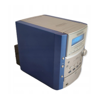
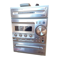
| dimensions | W: 170 mm, H: 243 mm, D: 273 mm |
| weight | 3.2 kg |
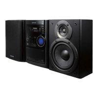
| woofer size | 120 mm, cone type |
|---|---|
| tweeter size | 50 mm, cone type |
| impedance | 4 Ω |
| maximum input power | 100 W |
| rated input power | 50 W |
| speaker dimensions | W: 174 mm, H: 243 mm, D: 225 mm |
| speaker weight | 2.9 kg (1 piece) |
List of included accessories with part numbers for the system.
Warnings regarding laser safety, product disposal, and battery handling.
Procedure to reset parental lock settings using a specific code.
Step-by-step guide for disassembling various parts of the main unit.
Diagnostic steps for the power supply unit (SMPS).
Checks for P-SENS, VKK, and MICOM circuitry issues.
Troubleshooting for MICOM, IC103, and the Front LCD display.
Diagnostic procedures for PWM modulation and power amplifier sections.
Troubleshooting for tuner, tape, and portable functions.
Diagnostic steps for tape recording and general power components.
A systematic flowchart for testing and debugging unit operations.
Specific steps for diagnosing issues with the USB interface.
Waveforms illustrating power-on sequence and USB data transfer.
Visual representation of tray open/close and MD sled action signals.
Waveforms for spindle, focus, and tracking signals during disc playback.
Waveforms showing initial focus acquisition signals (A, B, C, D).
Displays the RF signal for analog scope analysis, crucial for disc reading.
An overview of the main unit's circuitry and front panel component connections.
Diagram illustrating the DVD mechanism's interface and control signals.
Components for front, volume, jack, and I/O interfaces.
List of electrical components for the main unit's circuitry.
Components for the main unit and the Switch Mode Power Supply.
Components for the SMPS and DVD sections.
List of electrical components specifically for the DVD playback section.
Mechanical components for the DVD drive mechanism.
Mechanical components for the cassette deck mechanism.