617
679
626
J1
625
625
680
624
615
623
677
609
CD
CD
6
TAPE
2 3
MUTE
TUNER TAPE MUTE
ACTIVE
TUNER/BAND
STOP
ON/STANDBY
STANDBY/TIMER
VOLUME
STEREO
0
PHONES
PUSH OPEN
Indicator
(B12-0366-13)
Knob
(K29-7578-03)
Escutcheon
(B07-2455-02)
Cassette lid
(A53-2138-02)
Escutcheon
(B07-2454-02)
Panel *
(A60-)
Indicator
(B12-0366-13)
Knob
(K29-7573-04)
Knob
(K29-7567-04)
Panel
(A29-1056-13)
Phone jack
(E11-0282-05)
Indicator
(B12-0367-04)
612
J2
613
611
J1
J1
J5
671
640
+
-
+
-
MONITOR
OUT
REC OUT PLAY IN PLAY IN
VIDEO 1
VIDEO
AUDIO
REC
OUT
FRONT
SPEAKERS
(6 - 16Ω)
SUBWOOFER
(4 - 16Ω)
PLAY
IN
PLAY
IN
FM
75Ω
GND AM
VIDEO 1
AC 110–
120V
VIDEO 2
VIDEO 2
L
R
LR
ANTENNA
DIGITAL
OUT
OPTICAL
AC 220–
240V
AC 110–
120V
AC 220–
240V
Side plate R
(A50-1331-11)
Phono jack
(E63-0052-15)
Phono jack
(E63-1090-05)
Lock terminal board
(E70-0052-05)
Power cord bushing
(J42-0083-05)
AC power cord *
(E30-)
Side plate L
(A50-1330-11)
Oscillating module
(W02-1114-15)
Lock terminal board
(E70-0053-05)
Top plate
(A52-0365-02)
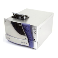
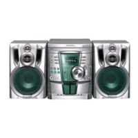
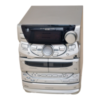
HIFI MINI COMPONENT SYSTEM
RXD-NV500/NV600
SERVICE MANUAL
(NV-500/600)
© 1999-7/B51-5559-00 (K/K) 3632
In compliance with Federal Regulations, following are reproduc-
tions of labels on, or inside the product relating to laser product
safety.
KENWOOD-Corp. certifies this equipment conforms to DHHS
Regulations No. 21 CFR 1040. 10, Chapter 1, Subchapter J.
DANGER : Laser radiation when open and interlock defeated.
AVOID DIRECT EXPOSURE TO BEAM.
Illust is RXD-NV600.
* Refer to parts list on page 35.