Do you have a question about the Kenwood SM-220 and is the answer not in the manual?
Warnings for high voltages, high vacuum CRT, and general safety precautions.
Detailed technical parameters and performance data of the SM-220 unit.
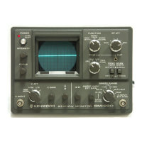
Summary of the SM-220's main functions and capabilities.
Specifications for the Cathode Ray Tube and its pinout diagram.
Visual representation of the SM-220's internal functional blocks.
Explanation of the basic principle of oscilloscope display operation.
Detailed description of the vertical and horizontal signal amplification paths.
Explanation of the monitor function and the two-tone generator circuits.
Description of the SM-220's power supply stages and voltages.
Diagrams showing front and rear views with labeled components.
Diagram illustrating the layout of the main printed circuit board.
Comprehensive list of all parts used in the SM-220 unit.
Guidelines for packaging the SM-220 for shipment.
Step-by-step guide for disassembling the front panel components.
Procedures for removing the graticule and the Cathode Ray Tube.
Lists necessary equipment for calibration procedures.
Procedure to center the trace when V. GAIN is adjusted.
Adjusts trace length for the horizontal sweep.
Compensates for high-frequency signal components in the vertical amplifier.
Corrects peaks or gain drop-off at high frequencies.
Sets output levels for 1 kHz, 1.575 kHz, and two-tone signals.
Diagnostic flowchart to identify and resolve common issues.
General introduction to the optional Pan Display unit for signal monitoring.
Detailed description of the BS-5 and BS-8 Pan Display units.
Specifications for the ceramic filters used in the Pan Display.
Diagram showing the layout of the Pan Display PC board.
Flowchart for troubleshooting and installing specific components.
Instructions for installing the optional BS-5/BS-8 Pan Display unit.
Procedures for calibrating the Pan Display option.
Guidelines for packing the SM-220 unit for safe shipping.
Detailed circuit schematic of the SM-220.
Circuit diagram specific to the BS-5 Pan Display option.
Circuit diagram specific to the BS-8 Pan Display option.