Do you have a question about the Kenwood T-599D and is the answer not in the manual?
Amplifies the AF signal from the microphone to prepare it for modulation.
Circuit generating the carrier frequencies for LSB, USB, CW, and AM transmissions.
The circuit responsible for modulating the AF signal with the carrier frequency.
Processes the modulated signal, filtering out unwanted sidebands and amplifying it.
Mixes VFO signal with IF signal, then filters to produce the 2nd IF signal.
Generates variable frequencies for tuning the transmitter to desired bands.
Mixes the 1st IF signal with the heterodyne crystal oscillator output.
Provides the second local oscillator signal for mixing with the IF signal.
Amplifies the SSB signal from the 2nd mixer to drive the final stage.
Amplifies the signal to the final output power level before transmission.
Manages automatic level control and bias for transmitter stages.
Controls transmission/reception switching based on voice input and prevents false triggering.
Generates an audio tone for monitoring CW keying and VOX operation.
Stabilizes DC supply voltages for various transmitter circuits.
Provides all necessary DC voltages from the AC mains.
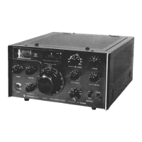
Identifies and explains controls located on the front of the transmitter.
Selects the emission mode (TUN, CW, LSB, USB, AM).
Selects the meter range (ALC, Ip, RF, HV) for monitoring.
Microphone connector for audio input.
Selects transmitter control mode (MAN, VOX, CAL).
Tunes the transmitter to the desired transmitting frequency.
Displays the main frequency setting, 100 kHz per revolution.
Displays fine frequency tuning, 25 kHz per graduation.
Provides index lines for reading frequencies in different modes.
Selects the amateur radio band (3.5 to 29.7 MHz).
Controls the ON-OFF power to the transmitter.
Switches between transmitting (SEND) and receiving (STBY) modes.
Tunes the final stage power amplifier for maximum drive.
Adjusts the final stage variable capacitor for tuning.
Adjusts the antenna load variable capacitor for matching.
Adjusts microphone gain to prevent overdrive and distortion.
Adjusts carrier output level for CW and AM modes.
Indicates ALC, plate current, RF output, or plate voltage.
Light indicating the VFO is operating.
Identifies and explains controls and connectors on the rear panel.
Antenna terminal for the receiver when sharing an antenna.
Antenna terminal for connecting antenna or dummy load.
Ground terminal for safety and interference reduction.
Connects the transmitter to the AC power source.
Service socket for deriving external AC power.
Selects the AC input voltage source (110-120V or 220-240V).
ALC input from a linear amplifier.
Controls the relay in a linear amplifier.
Connector for remote control of receiver and other functions.
Fuse holder for AC source protection.
Grille for the cooling fan compartment.
Jack for connecting a telegraph key.
Selects combined or separate operation with a receiver.
Terminal for motor fan supply.
Switch for enabling/disabling a VHF transvertor.
Output terminal for a transvertor.
Lists accessories supplied with the transmitter.
Recommends suitable locations for installing the transmitter.
Details power requirements and voltage considerations.
Discusses antenna requirements for optimal performance.
Discusses microphone selection and sensitivity.
Explains how to connect to receivers and linear amplifiers.
Details the functions of each pin on the REMOTE connector.
Specifies initial settings for controls before operation.
Illustrates how to connect the T-599D with the R-599D receiver.
Step-by-step guide for adjusting transmitter settings.
How to set microphone gain and input levels.
Specific adjustments for AM mode operation.
How to use the VOX feature for hands-free transmission.
How to use the push-to-talk function.
Notes on operating with slow scan television equipment.
Advice for new amateur radio operators.
Procedure for calibrating the receiver using the transmitter.
How to read frequencies and calibrate the main dial.
How to set and interpret the RF range meter reading.
How to use the ALC meter for optimal transmission.
Procedure for adjusting bias voltage, especially after tube replacement.
How to adjust the side tone volume.
Adjusting the carrier oscillator for oscillation and frequency.
Balancing the modulator to the carrier for proper signal quality.
Adjusting oscillator transformer cores for maximum output.
Adjusting the heterodyne crystal oscillator frequency.
Tuning the driver stage coils for maximum output.
Adjusting the neutralizing circuit to prevent self-oscillation.
Adjusting AM modulation level for optimal output.
Troubleshooting common issues caused by incorrect adjustments.
Symptoms of failure in carrier, VFO, or heterodyne oscillators.
Symptom of unbalanced carrier from the modulator.
Symptom of excessively high AM carrier level.
Symptoms of reduced output due to IF stage issues.
Symptoms of improper neutralization in the final stage.
Symptoms of improper bias circuit operation.
Symptoms of improper VOX circuit operation.
Effects of low input line voltage on transmitter performance.
Procedures for maintaining the transmitter's condition.
Instructions for safely removing the transmitter's cabinet.
Notes on replacing and maintaining tubes and transistors.
Guidelines for replacing faulty resistors and capacitors.
Maintenance recommendations for gears and tuning mechanisms.
Instructions for replacing the pilot lamp.
How to clean the transmitter's exterior and interior.
| Brand | Kenwood |
|---|---|
| Model | T-599D |
| Category | Transmitter |
| Language | English |