
J
JoseSep 13, 2025
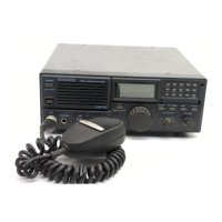
Como Abrir la ganancia del micrófono en el tk80, gracias
Como Abrir la ganancia del micrófono en el tk80, gracias
Recommended safety precautions for servicing and operating the equipment.
Procedures for accessing different operating modes like User, Dealer, Service, and Reset.
Steps to enter dealer mode and access memory channel selection.
Mode for writing alphanumeric display data up to 7 digits to memory channels.
Mode enabling users to select various settings for individual needs, with a list of modifiable items.
Details on performing All Reset and Battery Reset to restore factory default settings.
Mode for selecting memory channels to write frequency and information.
Mode for writing the transmit power limit (e.g., 100W, 50W) to memory channels.
Explanation of how to use VFO functions and select step frequencies.
Overview of dealer mode functions for customizing settings like frequency and power.
Mode for writing receive frequencies to memory channels, digit by digit.
Mode for selecting dealer-set functions for users, with a list of configurable items.
Mode for writing transmit frequencies to memory channels, digit by digit.
Mode for writing the type of emission (USB, LSB, AM, CW) to memory channels.
Step-by-step instructions for installing the optional Antenna Tuner unit.
Procedures for installing the optional TCXO (Temperature Compensated Crystal Oscillator).
Step-by-step instructions for installing the optional Selective Call unit.
Instructions for installing the optional IF filter YK-107C.
Instructions for installing the optional IF filter KIF-1.
Explanation of the TK-80's double conversion receiver and frequency configurations.
Description of LO2 signal generation and its output from CN502.
Overview of the receiver circuit with double conversion and IF stages.
Detailed explanation of the receiver front-end signal path through band-pass filters and mixers.
Details on the TK-80's PLL circuit, block diagram, and frequency configurations.
Explanation of the CAR signal generation and its use in FSK and ABSL signals.
Detailed explanation of the noise blanker circuit and its control of the TX-RX unit.
Description of the 20MHz crystal oscillator circuit and its optional TCXO replacement.
Details on the DDS circuit configuration for high-speed circuits and large-capacity ROM.
Explanation of LO1 signal generation using VCOs and mixing for frequency locking.
Description of components used in the Final Unit, including ICs, Qs, and Diodes.
Description of various IC components, mixers, and oscillators used in the unit.
Description of transistors, switches, and VCOs used in different circuit blocks.
Description of diodes such as voltage limiters, surge absorbers, and Zener diodes.
Description of components used in the Control Unit, including ICs, Qs, and Diodes.
Description of transistors and amplifiers used in various circuit stages.
Description of diodes including voltage limiters, surge absorbers, and Zener diodes.
Description of diodes related to DDS register selection and VCO control.
Description of components used in the TX-RX Unit, including ICs and Amplifiers.
Details on entering and operating the service adjustment mode, including EEPROM writing.
Section detailing adjustment procedures for the transmitter.
Detailed menu of adjustable parameters, covering microphone sensitivity and power settings.
Procedure for adjusting transmitter power output levels from 100W down to 3.75W.
Procedure for adjusting transmitter output power across different modes and levels.
Description of the AT TUNE switch function and initial state.
Explanation of the auto tuning process for matching circuits using motors and CPU control.
Procedure for adjusting the KPE-1 unit's frequency and tracking bandwidth.
| transmitter frequency range | 1.8~2.39999MHz, 3.5~4.49999MHz, 6.0~7.99999MHz, 11.0~14.49999MHz, 16.0~21.49999MHz, 24.0~29.99999MHz |
|---|---|
| receiver frequency range | 0.5~29.99999MHz |
| modes | J3E (SSB), A1A (CW), A3E (AM), F1B (FSK), J2B (AFSK) |
| power requirement | 13.6V DC ± 15% (negative ground) |
|---|---|
| current drain receive | Less than 1.45A |
| current drain transmit | Less than 20.5A |
| sensitivity SSB/CW/FSK (10dB S/N) | Less than 1µV (0.5~1.79999MHz) |
|---|---|
| sensitivity AM (10dB S/N) | Less than 7.94µV (0.5~1.79999MHz) |
| spurious response IF image ratio | More than 70dB |
| RF power output SSB/CW/FSK | 100W |
|---|---|
| AM (unmodulated signal) | 25W |
| carrier suppression | More than 40dB |
| dimensions (W x H x D) | 270 x 96 x 271 mm |
|---|---|
| weight (net) | 5.2kg |
| antenna impedance | 50Ω |