Do you have a question about the Kenwood TRC-70 and is the answer not in the manual?
Procedures for removing the radiotelephone covers.
Steps to remove the sub chassis from the radiotelephone.
Adjusting beep tone and tone levels using VR7 and VR6.
Diagrams and pin descriptions for microphone, power, and antenna connectors.
Basic connection instructions for power and antenna.
Recommendations for antenna connection types and placement.
Details the frequency setup for the TRC-70's double conversion system.
Explains the signal paths for receiving and transmitting operations.
Describes the Phase Locked Loop system and its constituent loops.
Covers CAR stop, unlock, control unit, and bus operation circuits.
Details control unit configuration, bus operation, and key scan.
Explains data backup, system reset, and signal switching mechanisms.
Covers squelch, noise blanker, dimmer, and tone output functions.
Lists and describes the functions of various unit terminals.
Lists components and their use in the final unit.
Lists components and their use in the control unit.
Lists components and their use in the TX-RX unit.
Lists components for Side Tone, DC-DC, Fan & Temp, and VCO units.
Explains capacitor codes, values, and tolerances.
Explains resistor codes, values, and tolerances.
Details chip resistor identification and parameters.
Lists parts for the main radiotelephone unit.
Lists parts for the final unit.
Lists parts for the control unit.
Lists parts for the TX-RX unit.
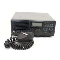
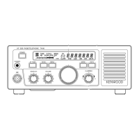
Identifies controls on the front and rear panels.
Safety warnings and required test equipment for alignment.
General alignment steps, views, and preparations.
Steps for adjusting receiver circuits.
Steps for adjusting the S-meter.
Steps for adjusting transmitter functions.
Procedures for adjusting high, medium, and low power outputs.
Adjusting transmitting meter and frequency characteristics.
Adjusting protection circuits and carrier suppression.
Lists terminal functions for the Final Unit.
Lists terminal functions for the Control Unit.
Lists terminal functions for the TX-RX Unit.
Component layout for LCD, Side Tone, DC-DC, Fan/Temp, VCO units.
Component and foil side views of the Control Unit.
Component and foil side views of the TX-RX Unit.
Electrical schematic for the Final Unit.
Electrical schematic for the Control Unit.
Electrical schematic for the TX-RX Unit.
Explains the tuning, interface, and operational circuits of the MAT-100.
Steps for automatic and manual antenna tuning.
Describes control signals and tuning modes.
Details the pins and functions of the control cable.
Explains PI and L-type matching circuit selection.
Explains the sensor block's function in impedance matching.
Describes the circuit that protects against excess power.
Explains how the frequency is read and processed.
Details the digital circuit's ICs and configuration.
Details the analog-to-digital converter circuit.
Explains how data is output to other circuits.
Describes how CPU operation modes are set.
Explains CPU standby modes and interface signals.
Describes the LED indicators and their control.
Explains manual and auto mode operations of the LED unit.
Lists components for Ant Module and LED units.
Lists parts for the MAT-100 tuner.
Provides guidance on installing the MAT-100 tuner.
Guidelines for antenna and coupler installation.
How to connect the control cable.
Steps to perform manual tuning of the antenna tuner.
Technical specifications for the automatic antenna tuner.
| Brand | Kenwood |
|---|---|
| Model | TRC-70 |
| Category | Cordless Telephone |
| Language | English |