PXL-500 / PXL-510 Tiger Controller
Quick Start Guide
Page 8 of 24 P/N: 01918-001 Rev. A
• The "B" input device is wired to TB6.
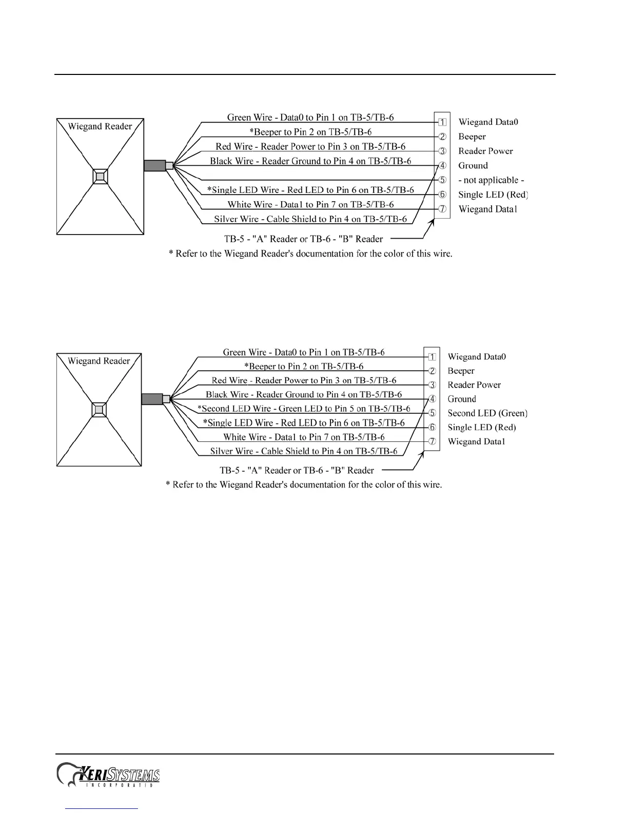
Figure 5: Single-Line LED and Essex Keypad Wiegand Reader Connections
Make the following connections for a dual-line LED Wiegand device.
• The "A" input device is wired to TB5.
• The "B" input device is wired to TB6.
Figure 6: Dual-Line LED Wiegand Reader Connections
4.5 Connecting a Door Status Input
Each PXL-500/PXL-510 is shipped with an installation kit including all necessary terminal blocks and transorbs. One of
these terminal blocks has a jumper across pins 1 and 2. This terminal block is designated for use on TB-4. If a door switch
is not used on the controller, this jumper prevents a continuous door open status alarm from being received by the
controller. If a door switch is used, simply remove this jumper and install the door switch leads.
 Loading...