EasyManua.ls Logo

KES G1 User Manual

KES G1
5 pages
To Next Page IconTo Next Page
Page #1 background imageLoading...
Page #1 background image
Included in package:
G1 Gimbal head
1 packet of spare screws containing
2-
¼-20 x ¾ Flat head patch screws
1- ⅜-16 x ¾ Low head cap screw
10 YEAR GUARANTEE
This product is guaranteed to the original purchaser to
be free of defects in materials or workmanship for ten
years from the date of purchase. Products will be
repaired or replaced at our option.
If not purchased directly from Kirk Enterprise Solutions,
please keep your original receipt for warranty repair as
proof of purchase of original ownership will be required.
Please note
All knobs are captive, meaning they cannot come off
without damaging them. Do not attempt to remove the
knobs. This will damage the head and void the warranty.
Also the G1 head is lubricated at the factory and parts
that require lubrication are sealed. NO LUBRICATION IS
REQUIRED BY THE USER. Just keep the G1
components free from contamination to maintain smooth
action.
Kirk Enterprise Solutions 333 Hoosier Dr Angola In 46703 www.kirkphoto.com 260-665-3670
Please read these instructions to fully understand the functions and capabilities of your new G1 Gimbal head.
Question and Answer IconNeed help?

Do you have a question about the KES G1 and is the answer not in the manual?

KES G1 Specifications

General IconGeneral
BrandKES
ModelG1
CategoryCamera Accessories
LanguageEnglish

Summary

10 YEAR GUARANTEE

Warranty Policy Details

Product guaranteed for ten years against defects; repair or replacement at company's option.

Important Notes and Usage Precautions

Knob Handling

Knobs are captive; do not attempt removal to avoid damage and voiding warranty.

Lubrication Requirements

Head is lubricated at factory; no user lubrication required. Keep parts free from contamination.

G1 Gimbal Top Mount Setup Guide

Mounting and Initial Securing

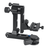
Attaching the gimbal head to the tripod and securing it using the pan base locking pin.

Lens Balancing Procedures

Balancing the lens horizontally and vertically using quick release adjustments and tilt axis control.

Adjusting Axis Tension

Applying tension to the tilt and pan axes for desired resistance and smooth operation.

How to Convert to a Side Mount Gimbal

Disassembly for Side Mount Conversion

Removing specific screws and parts from the vertical rail for side mount configuration.

Reassembly for Side Mount

Re-attaching the quick release clamp to the base for the side mount setup.

Side Mount Operation

Knobs and pins function as in top mount setup; balancing is similar to top mount procedures.

G1 Gimbal Disassembly for Storage

Removing the Quick Release Platform

Loosening the adjustment knob and sliding the platform off the vertical rail.

Detaching the Vertical Arm

Loosening the slide arm knob and pushing the safety pin to remove the vertical arm.