b - Lifting handle
SIDE VIEW:
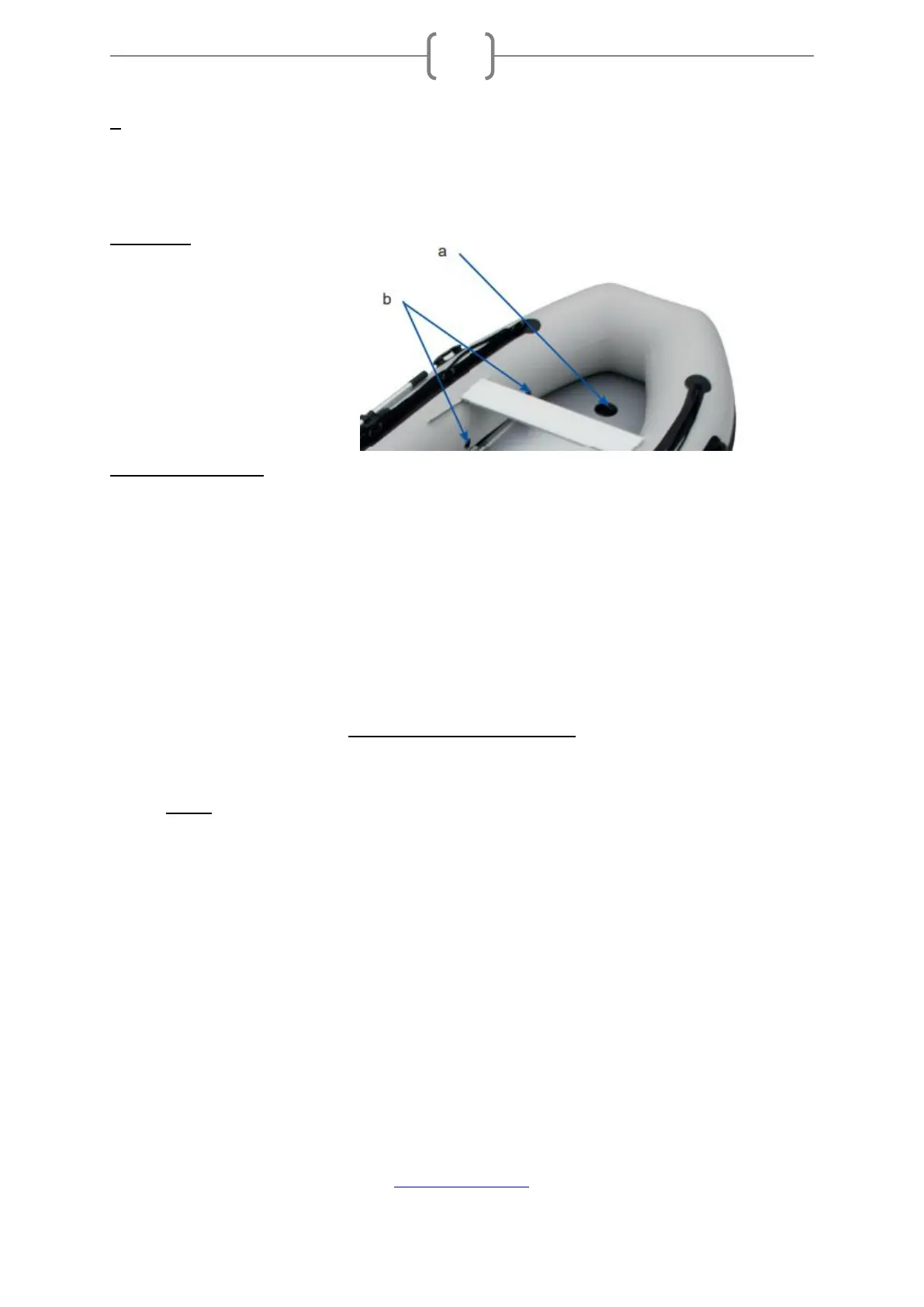
a – Keel air chamber valve
b - Air chamber valve
SCOPE OF DELIVERY
• Floats
• Aluminium floors
• Side joiner
• Repair kit
• Directions
• Transport bag
• Benches
• Paddle
• Foot pump with pressure gauge
ASSEMBLY AND DISASSEMBLY
INSTALLATION OF FLOOR SLABS
➢ NOTE: The floor plates must be installed in the boot before the boot is inflated.
1. Clear a flat surface that is clean and free of sharp objects.
2. Unfold the boat and lay it flat.
3. Attach the valves in the right place. Check that the cap seal fits correctly and
attach the valve holder to each valve.
4. Slide the front base plate (No. 1) into the bow. Position the opening above the
keel air chamber valve. Join the base plate (No. 2) with the front base plate.
5. Slide the rear base plate under the mirror holder (No. 4).
6. Join the remaining floor plates together. Position the middle floor plates so that
they form an inverted V-shape. Align the side edges of the base plates straight
and then press the V-profile to position the base plates evenly.
 Loading...