Do you have a question about the Keston C55: C55P and is the answer not in the manual?
| Model | C55P |
|---|---|
| Type | Condensing Boiler |
| Fuel Type | Natural Gas |
| Mounting | Wall-mounted |
| Water Connections | 22 mm |
| Maximum Working Pressure | 3 bar |
| Operating Temperature Range | 20 - 80°C |
| Flue System | Concentric or Twin Flue |
Procedure for safe handling and lifting of the boiler unit.
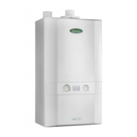
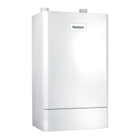
Overview of the Keston C40/C55 boiler concept, design, and features.
Diagram illustrating the boiler's internal layout and component connections.
Lists essential regulations and standards for boiler installation.
Technical specifications and dimensions of the C40 and C55 models.
Technical performance figures for C40 and C40P models on Nat Gas and LPG.
Technical performance figures for C55 and C55P models on Nat Gas and LPG.
Details of available accessories to complement the boiler installation.
Specifies required clearances for boiler installation and servicing access.
Identifies connection points for gas, water, air, flue, and electrical services.
Guidance on suitable locations for boiler installation, including safety considerations.
Details on power supply requirements and connection methods for the boiler.
Information on connecting external controls like programmers and thermostats.
Guidance on selecting the appropriate boiler size for system requirements.
Requirements for natural gas and LPG supply pressure and pipe sizing.
Guidelines for connecting the boiler to open vented and sealed water systems.
Requirements for flue pipe material, lengths, termination, and slope.
Information on the room-sealed appliance's air intake requirements.
Notes on installing the boiler within a compartment.
Instructions for connecting and routing the condensate drain pipe.
Instructions for fitting the wall mounting bracket correctly.
Steps for lifting and securing the boiler onto the wall bracket.
General advice on preventing debris ingress during pipe installation.
Guidance on connecting flue and air pipes, including replacement of old systems.
Detailed steps for assembling and connecting the condensate trap.
Instructions for connecting the flow and return pipework to the boiler.
Procedures for connecting the gas supply and checking its soundness.
Wiring instructions, safety precautions, and terminal connections for the electrical supply.
Procedures and considerations when replacing an existing boiler.
Steps for flushing the system and filling the boiler with water.
Checking the gas supply installation for soundness.
Performing preliminary electrical safety checks.
Note regarding LPG installations and model suitability.
Procedures for starting the boiler for the first time, including safety checks.
Steps for flushing the system while hot and refilling.
Measuring and adjusting CO2/CO levels for optimal combustion.
Verifying gas inlet pressure and joint soundness.
Procedure for determining gas input by timing the meter.
Explaining boiler operation, safety features, and maintenance to the user.
Describes the sequence of operations during boiler startup and running.
Explains the meaning of status codes displayed during normal boiler operation.
Details the boiler's reaction to faults and display of block codes.
How the boiler reacts to faults and displays block codes.
Explains error codes and what to do when the boiler enters a lockout state.
Diagram showing the functional electrical connections within the boiler.
Detailed wiring diagram illustrating all electrical connections.
Pictorial representation of the boiler's electrical wiring.
Provides exploded views of various boiler component assemblies.
Exploded view of the boiler's control components.
Exploded view of water, condensate, and flue system parts.
Exploded view of air intake and gas control components.
Exploded view of the boiler's external casing components.
A list of parts corresponding to the exploded diagrams.
Recommended inspection steps before performing annual service.
Detailed procedures for carrying out annual servicing of the boiler.
General advice that servicing must be done by a qualified person.
Essential safety precautions before working on the appliance.
Instructions on how to gain access to the boiler's internal components.
General guidance on the order and method of replacing parts.
Details procedures for replacing various electrical components.
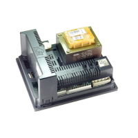
Procedure for replacing the boiler's control panel.
Steps for replacing the flow and return thermistors.
Procedure for replacing the cabinet temperature sensor.
Steps for replacing the flue protection thermostat.
Procedure for replacing the water pressure switch.
Steps for replacing the main control box.
Procedure for replacing the combustion blower.
Steps for replacing the gas control valve and venturi assembly.
Procedure for replacing the spark ignition/flame detection electrode.
Steps for removing and replacing the boiler's burner.
Procedure for replacing the heat exchanger.
Steps for removing and replacing the condensate trap.
Procedure for replacing the circulating pump.
Record for tracking annual servicing and maintenance of the heating system.