Do you have a question about the Keter DARWIN ELEVATED GARDEN BED and is the answer not in the manual?
Specifies the maximum weight load for the garden bed's shelves and structure.
Guides on using the floating leaf to check water levels for plant health.
Details on draining excess water and reusing it for other plants.
Explains the product's continuous water drainage and suitability for outdoor use.
Lists all parts required for assembly with labels and quantities.
Connects the base part M with leg parts LL and RL.
Attaches the shelf support part S to the leg parts LL and RL.
Secures the main frame components together using the provided fittings.
Reinforces the frame structure by fastening with screws (x4).
Installs the drainage caps (P x4) into the designated openings.
Inserts support posts into the frame for added structural integrity.
Attaches side panel B (x1) using connectors (C x1) and screws (x2).
Attaches side panel A (x1) using connectors (C x1) and screws (x2).
Attaches the second side panel B (x1) with connectors (C x1) and screws (x4).
Attaches the first side panel A (x1) using connectors (C x1) and screws (x4).
Attaches the second side panel A (x1) with connectors (C x1) and screws (x4).
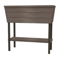
Positions the main planter box onto the assembled base structure.
Secures the planter box to the base using twelve screws (x12).
Installs the internal support grid (F x1) into the planter box.
Installs the water level indicator rod (WG x1) into its housing.
Attaches the water gauge knob to the side of the planter.
Provides contact details for customer service in various regions.
Details on product sustainability, recyclability, and responsible manufacturing.
Outlines consumer rights and guarantees under Australian law.
| Brand | Keter |
|---|---|
| Model | DARWIN ELEVATED GARDEN BED |
| Category | Lawn and Garden Equipment |
| Language | English |