9
EN
2 - INTRODUCING THE PRODUCT
Code Description
SUN4024 24 Vdc gear motor with mechanical limit switches, gate maximum weight 400 kg
SUN4224 24 Vdc gear motor with mechanical limit switches, gate maximum weight 400 Kg
SUN7024/SUN7024M* 24 Vdc gear motor with mechanical limit switches, gate maximum weight 700 Kg
SUN7224 24 Vdc gear motor with mechanical limit switches, gate maximum weight 700 Kg
SUN11024/SUN11024M* 24 Vdc gear motor with mechanical limit switches, gate maximum weight 1100 Kg
SUN52 230 Vac gear motor with mechanical limit switches, gate maximum weight 500 Kg
SUN82 230 Vac gear motor with mechanical limit switches, gate maximum weight 800 Kg
SUN122 230 Vac gear motor with mechanical limit switches, gate maximum weight 1200 Kg
SUN5024F 24 Vac gear motor with magnetic limit switches, gate maximum weight 500 Kg
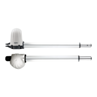
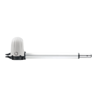
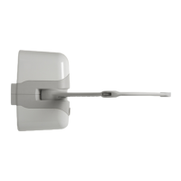
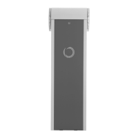
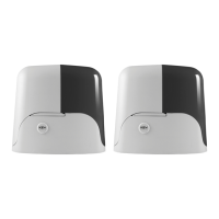
2.1 - Description of the product
The gear motor SUN is intended to be installed within systems for
the automation of sliding gates. The SUN gear motors have been
designed to automate sliding gates within the weight limits indicated
in the technical specications table.
The use of gear motors for applications which dier from those
indicated above is prohibited.
2.2 - Model and technical characteristics
3 - PRELIMINARY CHECKS
Before installing this product, verify and check the following steps:
- Check that the gate or door are suitable for automation
- The weight and size of the gate or door must be within the maxi-
mum permissible operating limits
- Check the presence and strength of the security mechanical stops
of the gate or door
- Check that the mounting area of the product is not subject to ood-
ing
- Conditions of high acidity or salinity or proximity to heat sources
could cause malfunction of the product
- Extreme weather conditions (for example the presence of snow,
ice, high temperature range, high temperatures) may increase the
friction and therefore the force required for the handling and initial
starting point may be higher than under normal conditions.
- Check that the manual operation of gate or door is smooth and
friction-free and there is no risk of derailment of the same
- Check that the gate or door are in equilibrium and stationary if left
in any position
- Check that the power line to supply the product is equipped with
proper grounding safety and protected by a magnetothermal and
dierential security device
- Provide the power system with a disconnecting device with a gap
of contacts enabling full disconnection under the conditions dictated
by the overvoltage category III.
- Ensure that all materials used for the installation comply with cur-
rent regulations
* magnetic limit switches
TECHNICAL DATA
MODELS SUN4024 SUN4224
SUN7024/
SUN7024M
SUN7224
SUN11024/
SUN11024M
SUN52 SUN82 SUN122 SUN5024F
TECHNICAL SPEC.
Speed cm/s 21 21 25 25 20 16 16 16 40
Torque Nm 12 12 26 26 38 16 23 35 23
Working cycle % 50 50 80 80 80 30 30 30 80
Control unit 14A CT10224 14A CT10224 14A CT102B CT102B CT102B 14A
Power supply
Vac
(Vdc)
230(24) 230(24) 230(24) 230(24) 230(24) 230 230 230 230(24)
Absorption A 1,1 1,1 1,5 1,5 1,3 1,3 1,9 2,6 1,5
Engine power W 250 250 345 345 300 300 450 600 345
Capacitor µF - - - - - 12,5 16 20 -
Thermoprotection °C - - - - - 150 150 150 -
Integrated lights SI - SI - SI - - - SI
Degree of protection IP 44 44 44 44 44 44 44 44 44
Dimensions (L-P-H) mm
330-210-
300
330-210-
300
330-210-
300
330-210-
300
330-210-
300
330-210-
300
330-210-
300
330-210-
300
330-210-
300
Weight Kg 12 12 12,5 12,5 13 15,5 16 16,5 12,5
Operating temperat. °C -20+55 -20+55 -20+55 -20+55 -20+55 -20+55 -20+55 -20+55 -20+55
Leaves max weight Kg 400 400 700 700 1100 500 800 1200 500
Sound emission level dB(A) ≤ 70 ≤ 70 ≤ 70 ≤ 70 ≤ 70 ≤ 70 ≤ 70 ≤ 70 ≤ 70