Do you have a question about the Key Automation SUN Series and is the answer not in the manual?
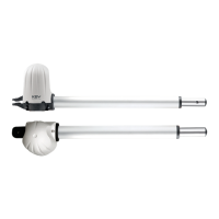
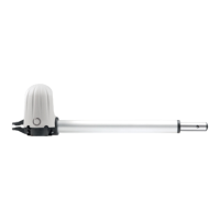
Overview of the SUN gear motor for sliding gates and its intended use.
Details on different SUN models, their specifications, and technical data.
Initial installation checks and product verification before mounting.
Instructions for fixing the base plate and preparing for the gear motor.
Steps to release the gearmotor for manual movement.
Steps for placing and securing the gearmotor onto the foundation plate.
Instructions for attaching the rack element to the gate.
How to position and fix the limit switch brackets.
Procedures for testing all system components and functions.
Steps for finalizing the installation and user handover.
Illustration showing the physical space requirements of the gear motor.
Diagram illustrating the standard mounting of the gear motor and components.
Illustration of the foundation box and its components.
Diagrams showing how to release the gearmotor mechanism.
Visual guide to operating the gearmotor release lever.
Step-by-step illustration for opening the gearmotor cover.
Diagram showing the wiring for the night light system.
Illustrations showing how to fix the gearmotor to the foundation plate.
Step-by-step illustration for closing the gearmotor cover.
Diagram showing the correct rack and pinion gear assembly.
Illustrations detailing the mounting of limit switches.
| Brand | Key Automation |
|---|---|
| Model | SUN Series |
| Category | Gate Opener |
| Language | English |