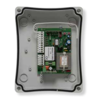
CT-400
• Centrale trifase/monofase per 1 motore 400/230 Vac no 2Cv con amperometrica.
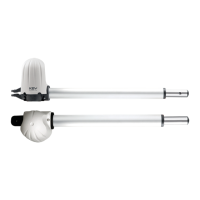
• Cancelli scorrevoli, porte veloci ad impacchettamento.
• Rilevazione elettronica ostacoli, freno interno ed esterno, 4 modi di funzionamento,
gestione codici radio integrato. Rilevamento Passaggio
Istruzioni ed avvertenze per l’installatore
U
V
Linea 230/400 Vac
Linea 230/400 Vac
T
SPIA
SPIA
-7-
-6-
-5-
-4-
-3-
-2-
Selezione 400 Vac
Selezione 230 Vac
Selezione Alimentazione
-10-
-9-
-8-
Lampeggiante o freno esterno
Fine Corsa APRE
Fine Corsa CHIUDE
Stop
Foto
Apre
-21-
-20-
-19-
-18-
-17-
-16-
-15-
-13-
W
-11-
-22-
-23-
-24-
-25-
Chiude
Start
Pedonale
Ingresso Costa
-1-
-12-
T
-26-
Linea 230/400 Vac
Lampeggiante o freno esterno
-29-
-30-
Alimentazione accessori 24 Vac
Alimentazione accessori 24 Vac
COM
COM
Comune
Comune
-14-
N.C.
N.A.
N.A. N.A. N.A.
M
Motore Trifase 400Vac
o Monofase 230Vac
Max 80W
TX
RX
*
*
Collegare questo punto al morsetto FTS
per avere il test sulle fotocellule.
Altrimenti collegarlo al morsetto 24V
**
Per avere il test collegare al morsetto 24V
OUT2
OUT2
GND
ANT
+ Antenna
- Antenna
Uscita contatto pulito secondo canale
Uscita contatto pulito secondo canale
Uscita 12Vac Max 1A
Uscita 12Vac Max 1A
12VAC
12VAC
Test
Test
-28-
-27-
**
.
Comando
CHIUDE
La centrale dispone di 2 pulsanti
che consentono di effettuare di-
rettamente l’apertura e la chiusu-
ra dell’automazione. Pag. 4
Comando
APRE