Do you have a question about the Key Automation RAY2224 and is the answer not in the manual?
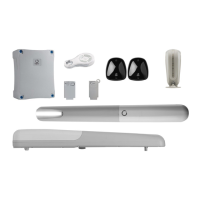
Provides a general overview of the RAY gear motors and their intended use for automated swing gates.
Details the different RAY models, their specifications, and technical data in a comparative table.
Covers general installation precautions, compatibility checks, and safety requirements before mounting the gear motor.
Details the procedure for mounting the rear fixing bracket for inward opening gates, referencing graphical aids.
Explains how to attach the front fixing bracket to the door leaf for inward opening installations.
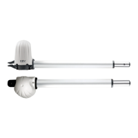
Provides instructions for installing the rear fixing bracket for outward opening gates, including accessory usage.
Describes the method for fixing the front bracket to the leaf for outward opening gates, ensuring correct alignment.
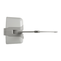
Guides the user through the physical mounting of the gear motor unit onto the prepared brackets.
Details how to connect the power cable and wires to the terminal block according to the wiring diagrams.
Explains the procedure to adjust the mechanical limit switches for precise opening and closing points.
Provides instructions on how to safely replace the LED components on the 24 Vdc models.
Outlines the essential tests to perform on all system components to ensure safety and functionality before commissioning.
Details the final steps of preparing the technical file, attaching identification plates, and user training.
| Power supply | 230V AC |
|---|---|
| Motor power supply | 24V DC |
| Protection class | IP44 |
| Maximum Current | 10A |
| Operating temperature | -20°C to +55°C |
| Contact Rating | 10A |