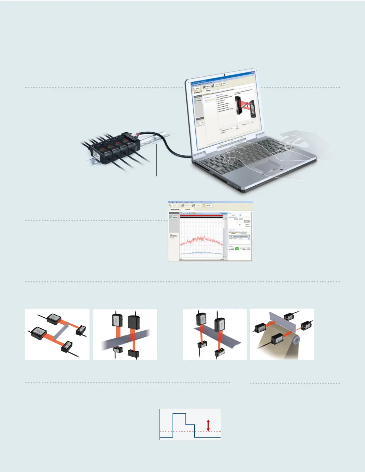
Reading and Writing Settings
The user can enter all settings including the measurement modes
into a PC and then transfer them to the sensor. The management
of setting data is simple and very convenient when two or more
sensors are used.
Monitoring Function
Measurement conditions such as the waveforms of received
light can be displayed in real time. The mounting and
sensitivity settings can also be adjusted more precisely.
Calculation Function
Addition mode
(if a measurement target is large)
SETTING EXAMPLE 1
(length)
SETTING EXAMPLE 2
(width)
Subtraction mode
(to measure the difference in level or inclination)
SETTING EXAMPLE 1
(inclination)
SETTING EXAMPLE 2
(difference in thickness)
Sensitivity Setting
The set value used to judge whether light enters or is blocked, based on the amount of light
received by the CCD, is called the binarization level. The amount of light received when
the reference waveform is registered is regarded as the 100% level. The light is judged
to be blocked if the amount of light is less than the
specified binarization level. The IG Series initially sets a
binarization level of 25% and the user can change the
level according to the application.
Zero Shift Function
This function shifts an internal
measurement value to 0 (to offset the
value). When the target value is changed,
this function can be used to shift an
internal measurement value to the new
target value.
The configuration software, IG Configurator, allows for a wide range of settings to be made
including the monitoring of the waveforms of received light and the measurement modes.
Received light level
Can be changed
freely
CCD position
100%
25%
0%
EVEN MORE USEFUL WHEN CONNECTED TO A PC
RS-232C communication unit
DL-RS1A
10
 Loading...