Do you have a question about the Kichler Lighting Cameron and is the answer not in the manual?
Ensure power is off before starting and wiring complies with codes. Use qualified electricians.
Suitable for use with solid-state speed controls.
Use specific screws for mounting and ensure outlet box supports 50 lbs. Use CUL Listed boxes.
Maintain 7 ft clearance, do not reverse switch while in motion, avoid objects in blade path.
Use only with light kits marked "Suitable for Use in Wet Locations".
Be cautious when cleaning. Use a dry or lightly damp cloth. Do not use water or detergents.
Wire conductors upward, spread wires apart by type (ground/white vs. black).
Electrical diagrams are reference only. Use CUL Listed kits and General Use Switches.
Do not bend blade brackets. Do not insert objects in the path of the blades.
Unit has a wattage limiting device. Exceeding 190 watts disables light fixture.
Secure outlet box directly to structure, ensuring it supports 50 lbs. Do not use plastic boxes.
A longer downrod may be needed for proper clearance on sloped ceilings.
Consider a "Joist Hanger" for outlet box support if needed, designed for ceiling fans.
Remove the decorative canopy bottom cover by turning it counterclockwise.
Remove ceiling mounting bracket by saving one screw and loosening the other.
Pass the 120 volt supply wires from the outlet box through the center of the mounting bracket.
Attach the ceiling mounting bracket to the outlet box using provided screws and washers.
Remove hanger ball by loosening set screw, removing cross pin, and sliding ball off rod.
Loosen set screws, remove hitch pin and retaining clip from motor assembly coupling.
Feed wires through downrod, thread downrod into coupling, align hitch pin holes, and secure.
Slip coupling cover, canopy cover, and canopy onto downrod. Thread hanger ball and secure.
Lift motor assembly, place hanger ball into mounting bracket, and rotate until "Check Tab" locks.
Attach wood screw and washers to ceiling joist next to mounting bracket, do not tighten.
Adjust cable length, form a loop, tighten clamp, and place loop over wood screw.
Set Dip Switch #5 to X position to disable dimming for CFL lamps.
Ensure transmitter and receiver frequency dip switches are set to the same position.
Insert receiver into ceiling mounting bracket with flat side facing ceiling. Extend black antenna.
Connect fan wires (black to "TO MOTOR L", blue to "FOR LIGHT") to receiver.
Connect ceiling wires (black to "AC IN L", white to "AC IN N") to receiver.
Connect ground wires from outlet box and mounting bracket. Tuck wires neatly into box.
Tuck all electrical connections neatly into the ceiling outlet box.
Slide canopy up, align keyhole slot over screw, rotate to lock, then secure with remaining screw.
Align canopy cover, insert screw heads into cover, and rotate clockwise to secure.
Attach each blade to a blade bracket using screws and rubber washers. Ensure straightness.
Attach each assembled blade to the motor using the pre-installed mounting screws.
Loosen two mounting screws on the motor shaft's mounting ring and remove the third screw.
Place light plate keyholes over screws, turn to lock, tighten screws, and replace third screw.
Connect white wires and black wires between socket plate and fan using provided connectors.
Tuck connections, align socket plate keyholes, turn to lock, and secure with three screws.
Install the three 40 Watt/E12 T3 Krypton lamps.
Raise the glass shade and turn clockwise until snug. Do not overtighten.
Replace existing wall plate and switch. Wire nut black leads, install metal and wall plates.
Mark location on flat surface, use anchors/screws to mount wall plate.
Insert transmitter into wall plate, bottom first, then press top. It functions in-place or handheld.
To remove, push the release button, and the transmitter will detach.
| Brand | Kichler Lighting |
|---|---|
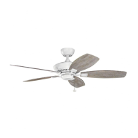
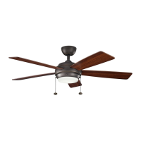
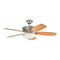
| Model | Cameron |
| Category | Fan |
| Collection | Cameron |
| Blade Span | 52 inches |
| Number of Blades | 5 |
| Motor Type | AC |
| Downrod Length | 4.5 inches |
| Voltage | 120V |
| Light Included | Yes |
| Reversible Motor | Yes |
| Finish | Brushed Nickel |
| Mounting Type | Ceiling |
| Warranty | Lifetime Motor Warranty |