4
QSCOMPONENTSYSTEM
CROSSOVER CONFIGURATION
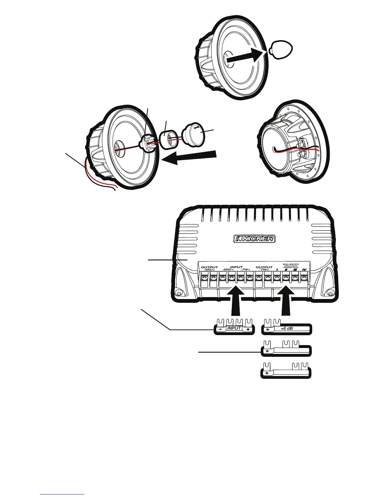
The KICKER QS crossover can be confi gured as a conventional 2-way crossover by installing the
included INPUT jumper into the - MID + -TW + input terminals as shown in Fig. 2. In this confi guration,
the amplifi ed signal from your source unit or amplifi er should be wired to the + and - terminals indicated on
the INPUT jumper.
The QS crossover can also be confi gured for bi-amp wiring by removing (or simply not installing) the
INPUT jumper. To use the bi-amp confi guration, you must connect two amplifi ed signals to each
crossover (you will need at least four amplifi er channels). Install one of the included tweeter output-
level jumpers (0 dB, +3 dB, or +6 dB) to adjust the tweeter output level. Installing jumpers with higher
numbers will result in more volume from the tweeter.
Step 1
Steps 2–6
Step 7
tweeter
tweeter post
coaxial mounting adapter
tweeter lead
wires
QS crossover
0 dB
+3 dB
INPUT jumper.
Install only for 2-way confi gurations;
do not install if bi-amping.
tweeter output-level jumpers.
One of these jumpers MUST be installed. Higher
numbers mean more volume from the tweeter.
Fig. 2
Fig. 1
Confi guring the QS for
Coaxial Operation
2009 QS Multilingual h01.indd 4 11/21/2008 10:54:27 AM