3-1690-FM200M-000 September 2004
FM-200
®
ECS Series Engineered Fire Suppression Systems
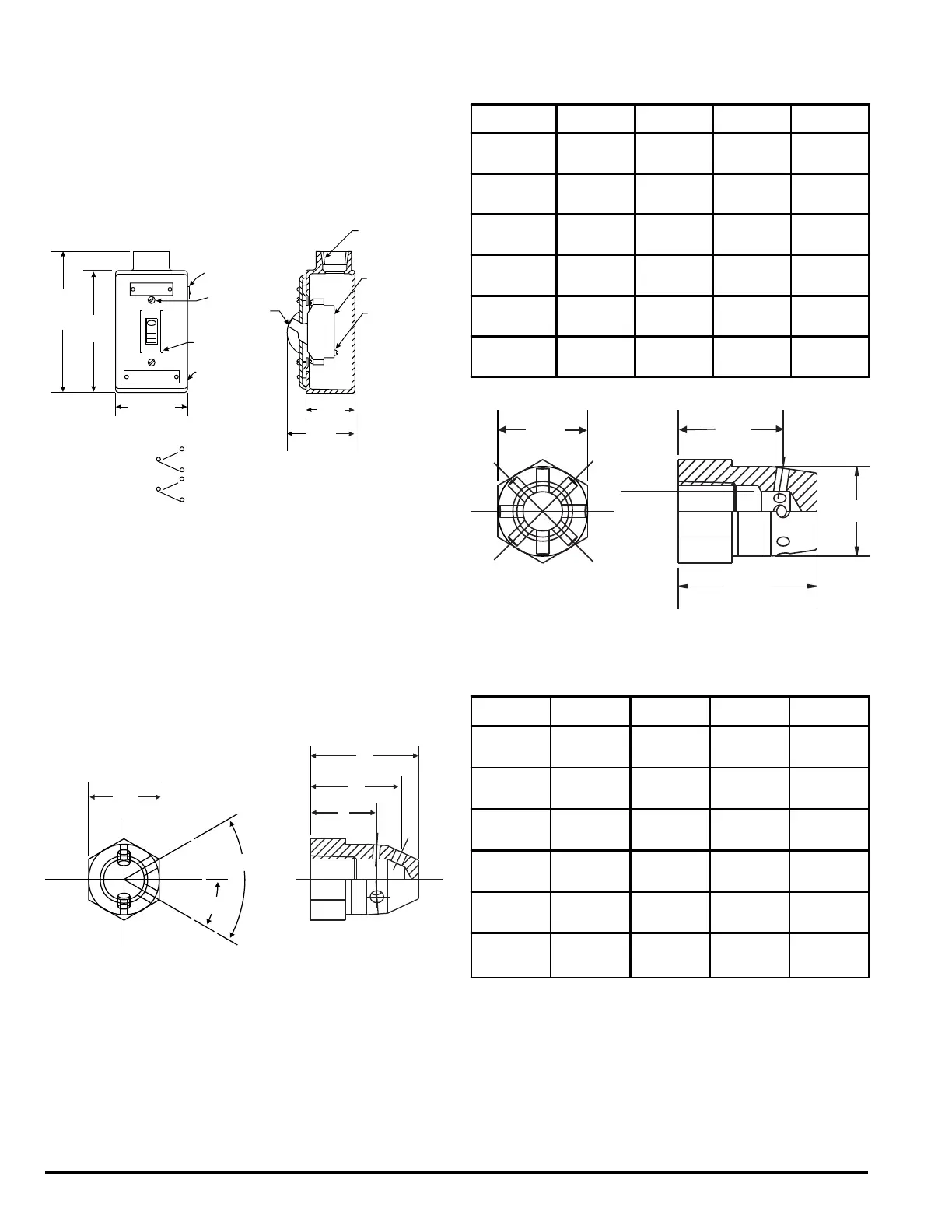
3-3.7.11 MAIN-TO-RESERVE TRANSFER SWITCH,
P/N 802398
The Main-to-Reserve Switch is installed on systems hav-
ing main and reserve cylinders. Placing the switch in either
the MAIN or RESERVE position provides uninterrupted fire
protection during system maintenance or in the event of a
system discharge (see Figure 3-35).
MAIN
RESERVE
TOGGLE
GUARDS
CONDULET
BOX
2.75"
(70 mm)
4.62"
(117 mm)
5.37"
(136 mm)
2-COVER SCREWS
NAMEPLATE
TOGGLE
SWITCH
SWITCH -
DOUBLE POLE
6-CONNECTION
¾” NPT FEMALE
FOR ELECTRICAL
CONNECTION
2.50"
(64 mm)
2.12"
(54 mm)
WIRING DIAGRAM
Switch Rating:
30 amps @ 120 Vac
COMMON
L-1
L-2
A-1
B-1
A-2
B-2
Figure 3-35. Main to Reserve Transfer Switch
3-3.7.12 DISCHARGE NOZZLES
The 180° and 360° discharge nozzles are designed to
provide the proper flow rate and distribution of FM-200
to flood a hazard area. The 180° nozzle is engineered to
provide a 180° discharge pattern for sidewall applica-
tions. The 360° nozzle offers a full 360° discharge pat-
tern for installations where nozzles are located in the
center of the hazard. See Figures 3-36 and 3-37 and
Tables 3-17 and 3-18 for further information.
B
C
D
A
30°
60°
Figure 3-36. 180° Discharge Nozzle
Table 3-17. Dimensions180° Discharge Nozzle
Pipe Size A B C D
½"
(12.20 mm)
1.25"
(31.75 mm)
1.25"
(31.75 mm)
1.687"
(42.84 mm)
2.0"
(50.80 mm)
¾"
(19.05 mm)
1.5"
(38.10 mm)
1.375"
(34.92 mm)
1.95"
(48.89 mm)
2.296"
(58.31 mm)
1"
(25.40 mm)
1.75"
(44.45 mm)
1.562"
(39.67 mm)
2.218"
(56.33 mm)
2.671"
(67.84 mm)
1¼"
(31.75 mm)
2.25"
(57.15 mm)
1.75"
(44.45 mm)
2.656"
(67.46 mm)
3.25"
(82.55 mm)
1½"
(38.10 mm)
2.5"
(63.5 mm)
1.95"
(48.89 mm)
2.95"
(74.93 mm)
3.625"
(92.07 mm)
2"
(50.80 mm)
3.0"
(76.2 mm)
1.968"
(49.98 mm)
2.875"
(73.02 mm)
3.656"
(92.86 mm)
C
D
B
A
Figure 3-37. 360° Discharge Nozzle
Table 3-18. Dimensions360° Discharge Nozzle
Pipe Size A B C D
½"
(12.20 mm)
1.250"
(31.75 mm)
1.468"
(31.28 mm)
1.937"
(49.19 mm)
1.250"
(31.75 mm)
¾"
(19.05 mm)
1.500"
(38.10 mm)
1.578"
(40.08 mm)
2.125"
(53.97 mm)
1.500"
(38.10 mm)
1"
(25.40 mm)
1.750"
(44.45 mm)
1.718"
(43.63 mm)
2.375"
(60.32 mm)
1.750"
(44.45 mm)
1¼"
(31.75 mm)
2.250"
(57.15 mm)
1.950"
(49.53 mm)
2.751"
(69.85 mm)
2.250"
(57.15 mm)
1½"
(38.10 mm)
2.250"
(63.50 mm)
2.000"
(50.80 mm)
2.937"
(74.59 mm)
2.500"
(63.50 mm)
2"
(50.80 mm)
3.000"
(76.20 mm)
2.062"
(52.37 mm)
3.125"
(79.37 mm)
3.000"
(76.20 mm)
 Loading...