4-8
90-FM200M-000 September 2004
FM-200
®
ECS Series Engineered Fire Suppression Systems
4-2.3.3 DURATION OF DISCHARGE
Per NFPA 2001, the liquid agent discharge shall be completed
in a nominal 10 seconds or less. Discharge times shorter than
10 seconds are desirable to minimize production of break-
down products. Discharge times as short as six seconds
should be considered when circumstances permit.
4-2.3.4 NOZZLE SELECTION AND PLACEMENT
There are two basic Kidde nozzle configurations:
1. The 360° nozzle, which provides a full 360° discharge
pattern designed for placement in the center of
the hazard.
2. The 180° nozzle, which provides a 180° discharge pat-
tern designed for placement adjacent to a side wall of
the hazard.
Use ECS Series software as a tool to determine the selec-
tion of the required orifice area and nozzle.
Maximum orifice area to pipe area ratio:
The ratio between the nozzle orifice area for a 360 de-
gree nozzle at the given node and the pipe cross sec-
tional area for the pipe segment preceding that nozzle
is 0.72, or 72%,
The ratio between the nozzle orifice area for a 180 de-
gree nozzle at the given node and the pipe cross sec-
tional area for the pipe segment preceding that nozzle
is 0.66, or 66%.
Minimum orifice area to pipe area ratio:
The ratio between the nozzle orifice area for a 360 de-
gree nozzle at the given node and the pipe cross sec-
tional area for the pipe segment preceding that nozzle
is 0.27, or 27%.
The ratio between the nozzle orifice area for a 180 de-
gree nozzle at the given node and the pipe cross sec-
tional area for the pipe segment preceding that nozzle
is 0.27, or 27%.
Nozzles are available in nominal pipe sizes of 1/2", 3/4, 1",
1¼", 1½" and 2".
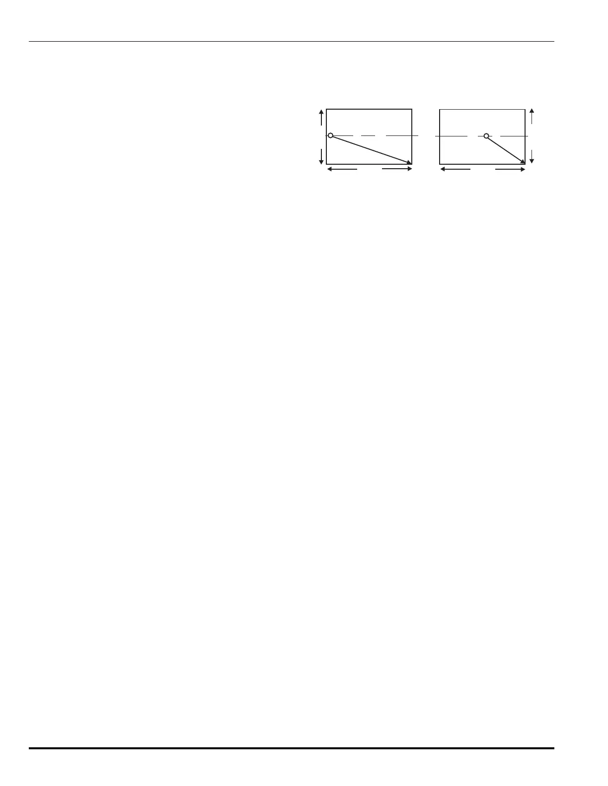
4-2.3.5 NOZZLE PLACEMENT
There are certain coverage and height limitations which
must be observed with each nozzle configuration to ensure
proper agent distribution.
44’
(13.3 m)
40’
(12 m)
180° Nozzle 360° Nozzle
d = 29.7´
(9.06 m)
d = 48.3´
(14.73 m)
44’
(13.3 m)
40’
(12 m)
Figure 4-3. Nozzle Placement and Coverage
Orientation-Nozzles must be mounted perpendicu-
lar to the ceiling or subfloor surface and oriented with
the orifices radiating symmetrically outward from the
pipe network.
Ceiling Clearance-Nozzles must be installed so that
the orifices are located 6 +/- 2 inches (0.15 +/- 0.05 m)
below the ceiling.
Maximum Height-The maximum protected height for
a single row of nozzles is 16 feet (4.87 m). The 16 ft.
(4.87 m) coverage height includes the 6 +/- 2 inches
(0.15 +/- 0.05 m) below the ceiling.
Nozzles may be tiered to accommodate enclosures with
ceiling heights greater than 16 ft. (4.87 m).
Minimum Ceiling Height-The minimum ceiling
height for UL Listed/FM Approved systems is
1 ft. (0.3 m).
Systems designed for enclosures 6 to 12 inches
(0.15 m to 0.3 m) are acceptable, but not UL Listed
or FM Approved.
180° Nozzles-180° nozzles must be located 12 +/- 2
inches (0.3 +/- 0.05 m) from a wall, with the orifices
directed away from the wall. The nozzle shall be lo-
cated as close to the center of the wall as possible, but
at least 1/3 of the way along the wall.
180° nozzles have a maximum coverage area defined
as any rectangle that can be inscribed in a semicircle
of distance 48.3 ft. (14.73 m, diagonal of a rectangle
20' x 44'). Refer to Figure 4-3 for further information.
180° nozzles may be used in a back-to-back configu-
ration. The nozzles should be place 1 to 2 ft. (0.3 m to
0.6 m) apart.
360° Nozzles-360° nozzles must be located as close
to the center of the enclosure as possible. 360° nozzles
have a maximum coverage area defined as any rect-
angle that can be inscribed in a circle of radius 29.7 ft.
(9.06 m, diagonal of a rectangle 20' x 22'). Refer to
Figure 4-3 for further information.
Multiple Nozzles-Nozzles whose discharge patterns
will intersect must be placed at least 10 ft. (3.3 m) apart
to assure adequate agent distribution.
 Loading...