4-9
September 2004 90-FM200M-000
FM-200
®
ECS Series Engineered Fire Suppression Systems
Walls and Obstructions-FM-200 discharged from the
nozzle requires a certain length from the nozzle to at-
omize into a gas. If the FM-200 comes into contact with
a surface before the agent is fully atomized, frosting
can occur. As a result, the concentration throughout
the enclosure will be less than required to appropri-
ately protect the space. Therefore, nozzles must be
located with at least four to six feet of clearance from
walls and/or significant obstructions (ex. high rise rack-
ing and columns). If this requirement cannot be met,
additional agent may be discharged to compensate for
this agent "loss".
Reduced Coverage Area-Consideration should be
given to reducing nozzle spacing when obstructions
that would impede the uniform distribution of FM-200
throughout the area are present. Nozzle coverage
area must be reduced to 25 ft. x 25 ft. for enclosure
heights six to twelve inches (7.5 m x 7.5 m for heights
0.15 to 0.3 meters).
Limits on Nozzle Conditions:
Minimum average nozzle pressure-The nozzle pres-
sure must be a minimum of 74 PSIG for the nozzle to
effectively disperse the agent and mix the agent into
the air of the enclosure being protected.
Maximum arrival time imbalance-The difference be-
tween liquid arrival times at two of the nozzles exceed
the 0.8 seconds allowed.
Maximum runout time imbalance-The difference be-
tween nozzle liquid runout times at two of the nozzles
exceed the 2.0 second allowed maximum.
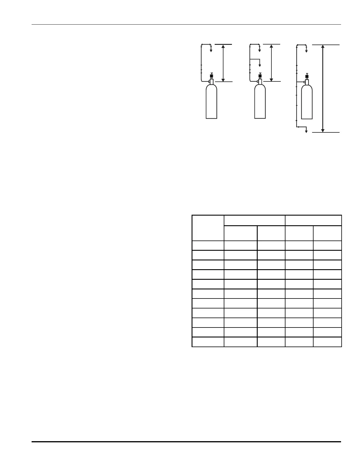
Maximum Elevation Differences in Pipe Runs:
If nozzles are only located above the container outlet,
then the maximum elevation difference between the
container outlet and the furthest horizontal pipe run or
discharge nozzle (whichever is furthest) shall not ex-
ceed 30 ft. (9 m).
If nozzles are only located below the container outlet,
then the maximum elevation difference between the
container outlet and the furthest horizontal pipe run or
discharge nozzle (whichever is furthest) shall not ex-
ceed 30 ft. (9 m).
If nozzles are located both above and below the con-
tainer outlet, then the maximum elevation difference
between the furthest horizontal pipe runs or discharge
nozzles (whichever is furthest) shall not exceed
30 ft. (9 m).
Note: If you have a system design that violates these lim-
its, then you must consult the factory to determine
what course of action should be taken (see Figure
4-4 for further clarification).
30’ Max
30’ Max
System With A
Single Row of Nozzles
System With A
Multiple Row of Nozzles
30’ Max
System With Ceiling
and Subfloor Nozzles
Figure 4-4. Nozzle Limitations
Note: Any system designed for a space less than
12 in. (0.3 m) in height is not a UL Listed or
FM Approved design.
4-2.3.6 PIPE SIZING
The following table may be used as an estimating guide for
sizing distribution piping.
Table 4-6. Kidde Pipe Size Estimating Table
Nominal
Pipe Size
(in.)
Flow Rate (lb./sec.) Flow Rate (kg/sec.)
Minimun
Design
Max. Nom.
Design
Minimum
Design
Max. Nom.
Design
1/2 1.0 3.0 0.5 1.4
3/4 2.0 5.5 0.9 2.5
1 3.5 8.5 1.6 3.9
1¼ 6.0 12.5 2.7 5.7
1½ 9.0 20.0 4.1 9.0
2 14.0 30.0 6.4 13.6
2½ 20.0 55.0 9.0 25.0
3 30.0 90.0 13.6 40.9
4 55.0 125.0 25.0 56.8
5 90.0 200.0 40.9 90.9
6 120.0 300.0 54.5 136.4
This table is intended for use as a guide only. The Kidde
ECS Series Flow Calculation Program must be used for
the final design.
 Loading...