4-15
September 2004 90-FM200M-000
FM-200
®
ECS Series Engineered Fire Suppression Systems
4-3.6 Installation of Pressure Actuation Pipe
The pressure actuation pipe must be 1/4-inch Schedule 40
or 80 pipe. The pipe or tubing must be routed in the most
direct manner with a minimum of fittings. Pipe and fittings
must be in accordance with the requirements listed in Para-
graph 4-2.5. Fittings can be flared or compression type.
The pressure-temperature ratings of the fitting manufac-
turer must not be exceeded.
Piping must be reamed free of burrs and ridges after cut-
ting, threading or flaring. Upon assembly, pipes must be
blown out with dry nitrogen or compressed air. Piping should
be securely braced and isolated from vibration, mechani-
cal or chemical damage.
4-3.7 Installation of Valve Outlet Adapter
WARNING
!
Always connect a valve outlet adapter into
system piping (union connection) before
connecting to an FM-200 cylinder.
Install valve outlet adapter (P/Ns 283904, 283905 and
283906) in system piping. Tighten securely.
Note: A groove-groove fitting is used in place of a valve
outlet adapter for the 3-inch valve and associ-
ated cylinders.
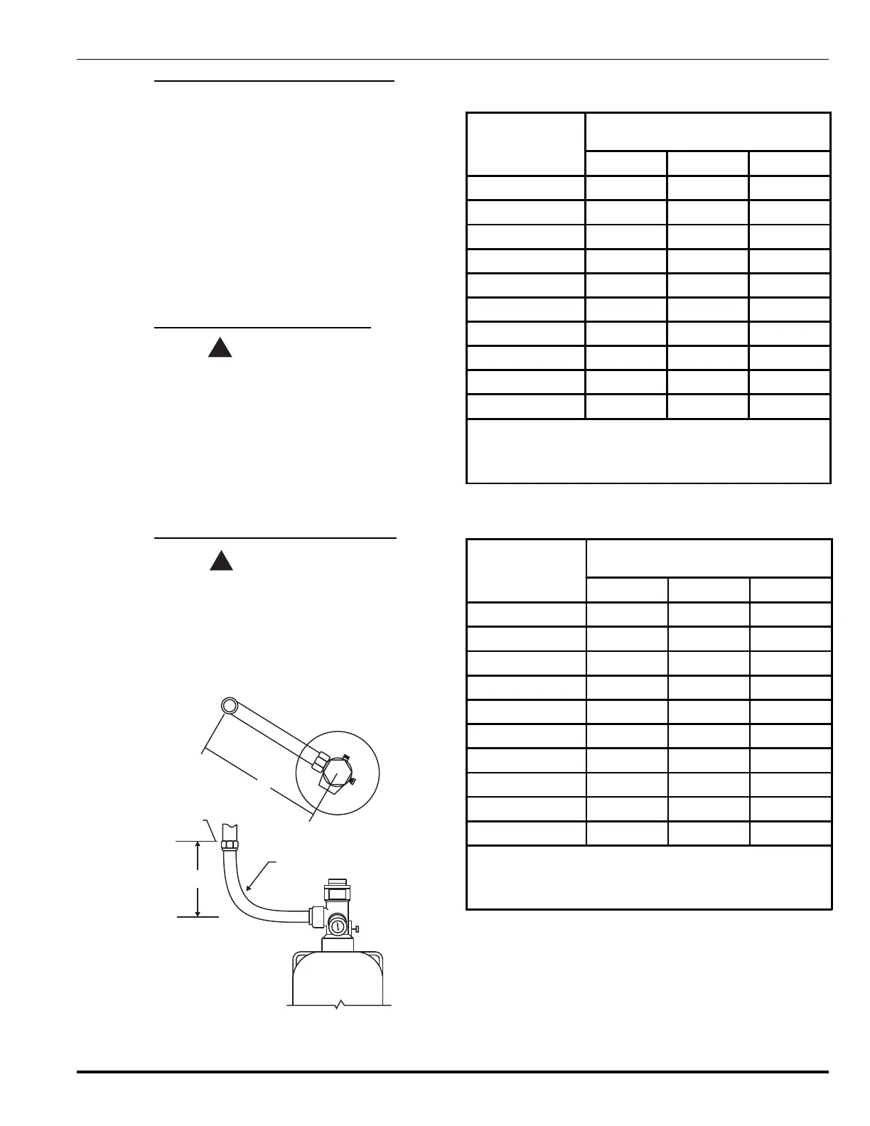
4-3.8 Installation of Flexible Discharge Hose
WARNING
!
Always connect the flexible discharge hose
into system piping before connecting to an
FM-200 cylinder.
Attach the flexible discharge hose from system piping or
El-check in the discharge manifold to the cylinder valve.
Tighten securely (see Figure 4-10 and Tables 4-8 and 4-9).
A
B
C (HOSE SIZE)
FACE OF
PIPE FITTING
Figure 4-10. Installation of the Flexible Hose
Directly Into System Piping
Table 4-8. Installation of the Flexible Hose Directly into
System Piping, Inches
Cylinder Capacity
Dimensions in Inches
ABC*
10 lb. 14 5/8 16 3/4 1 1/2
20 lb. 14 5/8 16 3/4 1 1/2
40 lb. 14 5/8 16 3/4 1 1/2
70 lb. 14 5/8 16 3/4 1 1/2
125 lb. 14 5/8 16 3/4 1 1/2
200 lb. 19 21 3/4 2
350 lb. 19 21 3/4 2
600 lb. (old style) 29 5/8 32 3/4 2 1/2
600 lb. (new style) 33 36 3
900 lb. 33 36 3
Note: Dimensions A and B must be maintained in order to obtain a
smooth radius in flexible loop.
* Hose may require an adapter to connect to system piping.
Table 4-9. Installation of the Flexible Hose Directly into
System Piping, Millimeters
Cylinder Capacity
Dimensions in Millimeters
ABC
10 lb. 371 425 38
20 lb. 371 425 38
40 lb. 371 425 38
70 lb. 371 425 38
125 lb. 371 425 38
200 lb. 483 552 51
350 lb. 483 552 51
600 lb. (old style) 752 832 64
600 lb. (new style) 838 914 76
900 lb. 838 914 76
Note: Dimensions A and B must be maintained in order to obtain a
smooth radius in flexible loop.
*Hose may require an adapter to connect to system piping.
 Loading...