4-16
90-FM200M-000 September 2004
FM-200
®
ECS Series Engineered Fire Suppression Systems
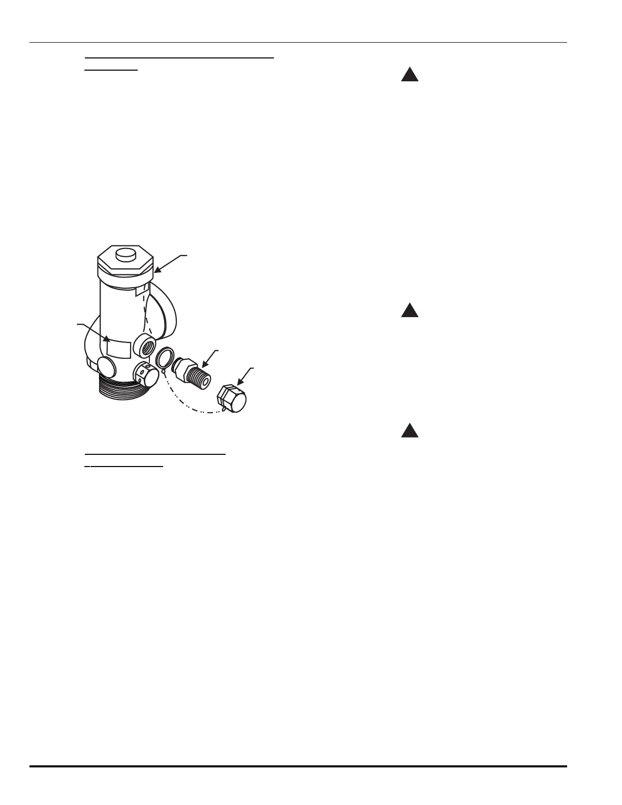
4-3.9 Installation of Master Cylinder Adapter Kit,
P/N 844895
Note: Master cylinder adapter installation can be accom-
plished safely with a pressurized cylinder.
1. Remove the 1/4-inch pipe plug from the slave actuation
port on the master cylinder valve (see Figure 4-11).
2. Before assembling the adapter to the cylinder valve,
apply Permacel No. 412D Teflon
®
tape to the male
threads on the adapter.
3. Ensure the cap is screwed onto the adapter outlet port
before assembling to the cylinder valve.
4. Install the adapter into the slave actuation port on the
master cylinder valve.
5. Attach the label to the valve body.
ADAPTER
CAP
VALVE
LABEL
Figure 4-11. Installation of Master Cylinder Adapter Kit
4-3.10 Installation of FM-200 Cylinder/
Valve Assemblies
The FM-200 cylinders should be located as close as pos-
sible to the protected hazard area. The assemblies should
be located in a place which is readily accessible for manual
actuation and inspection, service and maintenance. The
cylinders shall be located in an environment protected from
the weather, and where the ambient temperature does not
exceed 80°F (27°C) or fall below 60°F (16°C). External heat-
ing or cooling may be required to maintain this temperature
range. The following installation instructions must be fol-
lowed in the exact sequence outlined below to prevent ac-
cidental discharge, bodily injury and property damage.
4-3.10.1 SINGLE CYLINDER SYSTEMS
WARNING
!
Cylinders must be located and mounted
where they will not be accidently damaged or
moved. If necessary, install suitable
protection to prevent the cylinder from
damage or movement.
1. Position FM-200 cylinder in designated location and
secure in place with cylinder strap and attaching hard-
ware (see Figure 4-12 and Tables 4-10, 4-11 and
4-12). Orient cylinder with valve outlet angled toward
system piping.
2. Remove the safety cap from the cylinder valve
outlet port.
3. Connect a 1½-, 2-, 2½-, or 3-inch flexible discharge
hose or valve outlet adapter to the cylinder outlet port.
Note: If a valve outlet adapter is used, a union must be
installed in the discharge piping.
WARNING
!
Connect the discharge hose to system piping
before attaching it to the cylinder valve.
The valve outlet adapter must be connected
into system piping (union connection) before
attaching it to the cylinder valve.
4. Remove the protection cap from the cylinder valve ac-
tuation port.
WARNING
!
The control head must be in the SET position
(that is, the actuating pin must be in the fully
retracted or SET position) before attaching it
to an FM-200 cylinder in order to prevent
accidental discharge.
5. Install the control head to the cylinder valve actua-
tion port.
 Loading...