4-20
90-FM200M-000 September 2004
FM-200
®
ECS Series Engineered Fire Suppression Systems
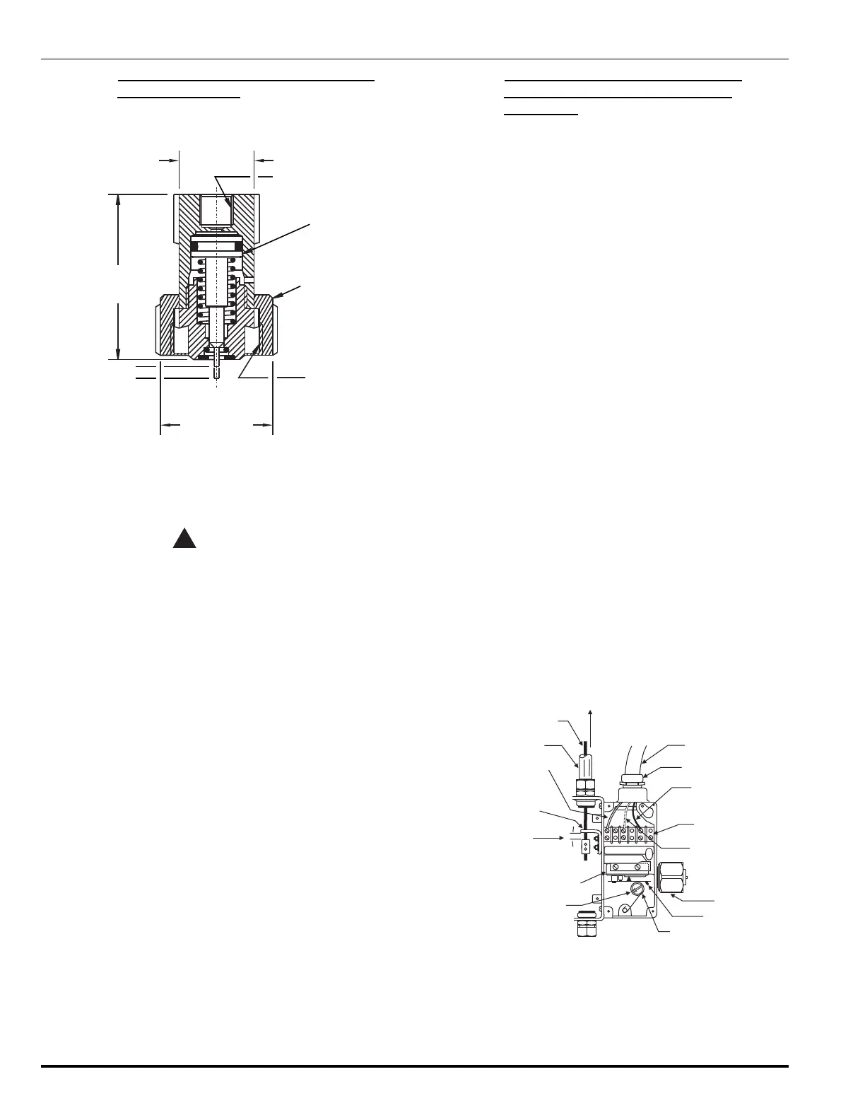
4-3.12 Installation of Pressure Operated Control
Heads, P/N 878737
1. Remove the protection cap from the cylinder actuation
port (see Figure 4-16).
1.250-18
UNEF-3B
SWIVEL NUT
PISTON
1/8"-27 NPT
PRESSURE INLET
SET
OPERATED
2.19"
(55.6 mm)
1.50" HEX
(38 mm)
1.00" HEX
(25.4 mm)
Figure 4-16. Pressure Operated Control Head
2. Install a pressure operated control head with flexible
actuation hose attached to the cylinder actuation port.
WARNING
!
Ensure that the pilot line is non-pressurized and
the actuating pins are in the retracted (SET)
position. Failure to follow this procedure will
cause the FM-200 cylinder to discharge
accidentally when the control head is installed
on the cylinder valve.
4-3.13 Installation of Electric/Cable Operated
Control Head, P/Ns 895630, 895627
and 895628
The following procedures must be performed before attach-
ing a control head to a cylinder valve (see Figure 4-17):
1. Remove the four screws holding the cable housing
cover on the control head. Remove the cover.
2. Position the control head in the approximately installed
position at the FM-200 cylinder valve control port but
do not assemble onto the actuation port of the FM-200
cylinder valve.
3. Check that the control head is in the SET position.
4. Assemble the pull cable conduit to the conduit connec-
tion on the control head.
5. Feed the cable into the control head through the hole
in the operating lever.
6. Feed the cable through the cable clamp. Pull the cable
taut, allowing approximately 1/4" to 1/2" clearance be-
tween the cable clamp and the operating lever. Tighten
the set screws in the cable clamp to secure the cable
to the clamp.
7. Cut off any excess cable.
8. Verify the manual remote cable operation to ensure con-
trol head actuates and all cable clamps are tight.
9. Pull the cable back to its normal set (non-operated)
position.
10. Reset the control head.
11. Replace the control head cover.
12. Examine the seal wire at the safety pull pin. Make sure
it is intact.
13. Make all electrical connections.
14. Assemble the control head to the cylinder valve actua-
tion port. Tighten the swivel nut securely.
1/2" E.M.T.
1/16” CABLE
PLUS OR HOT
CONNECTION
THREAD CABLE
THRU HOLE IN
OPERATING LEVER
POSITION CABLE
BLOCK APPROXIMATELY
AS SHOWN LEAVING
1/4” - 1/2” GAP
MICROSWITCH
INDICATOR AND
RESET STEM
FLEXIBLE CONDUIT
3/4” NPT BY FLEXIBLE
CONDUIT CONNECTOR
MINUS, NEUTRAL
OR GROUND
CONNECTION
TERMINAL STRIP
OPTIONAL CONNECTION
FOR MICROSWITCH
MICROSWITCH
LEVER
SWIVEL NUT
CAM
VIEW WITH COVER AND
NAMEPLATE REMOVED
DIRECTION
OF PULL
Figure 4-17. Electric/Cable Operated Control Head
 Loading...