4-19
September 2004 90-FM200M-000
FM-200
®
ECS Series Engineered Fire Suppression Systems
4-3.10.3 MAIN AND RESERVE SYSTEM
Install main and reserve systems as instructed in the
previous paragraphs.
4-3.11
Installation of Electric Control Heads
WARNING
!
Before installing a control head on an FM-200
cylinder valve, ensure the control head is in the
SET position (that is, the actuating pin is in the
fully retracted or SET position). Failure to
position the control head in the SET position
will result in accidental FM-200 cylinder
discharge when the control head is installed
on cylinder valve. Personal injury and/or
property damage could occur.
Electric Control Head, P/N 486500-01 is
designed for Kidde 1½", 2" and 2½" FM-200
cylinder valves only. Installing this control head
on any other device (for example, pressure
operated control head) will cause the device to
malfunction when the control head is actuated.
1. Remove the protection cap from the FM-200 cylinder
actuation port. Ensure the control head is in SET posi-
tion (that is, the actuating pin is in the fully retracted or
SET position).
2. Install the electric control head on the cylinder actua-
tion port. Tighten the swivel nut.
3. Make all electrical connections.
Note: P/N 486500-01 is a polarized control head. Im-
proper wiring will cause the device to malfunction.
CAUTION
!
The stackable control head (P/N 48650001)
cannot be used with the 3-inch valve cylinder
(P/Ns 90-100600-100, 90-100601-100, 90-
100900-001 and 90-100901-001). The stackable
control head does not have sufficient force
to activate the 3-inch valve (P/N 90-17000-000)
and may result in system failure. Use the
electric/manual control heads (P/N[s] 8901XX)
with the 3-inch valve.
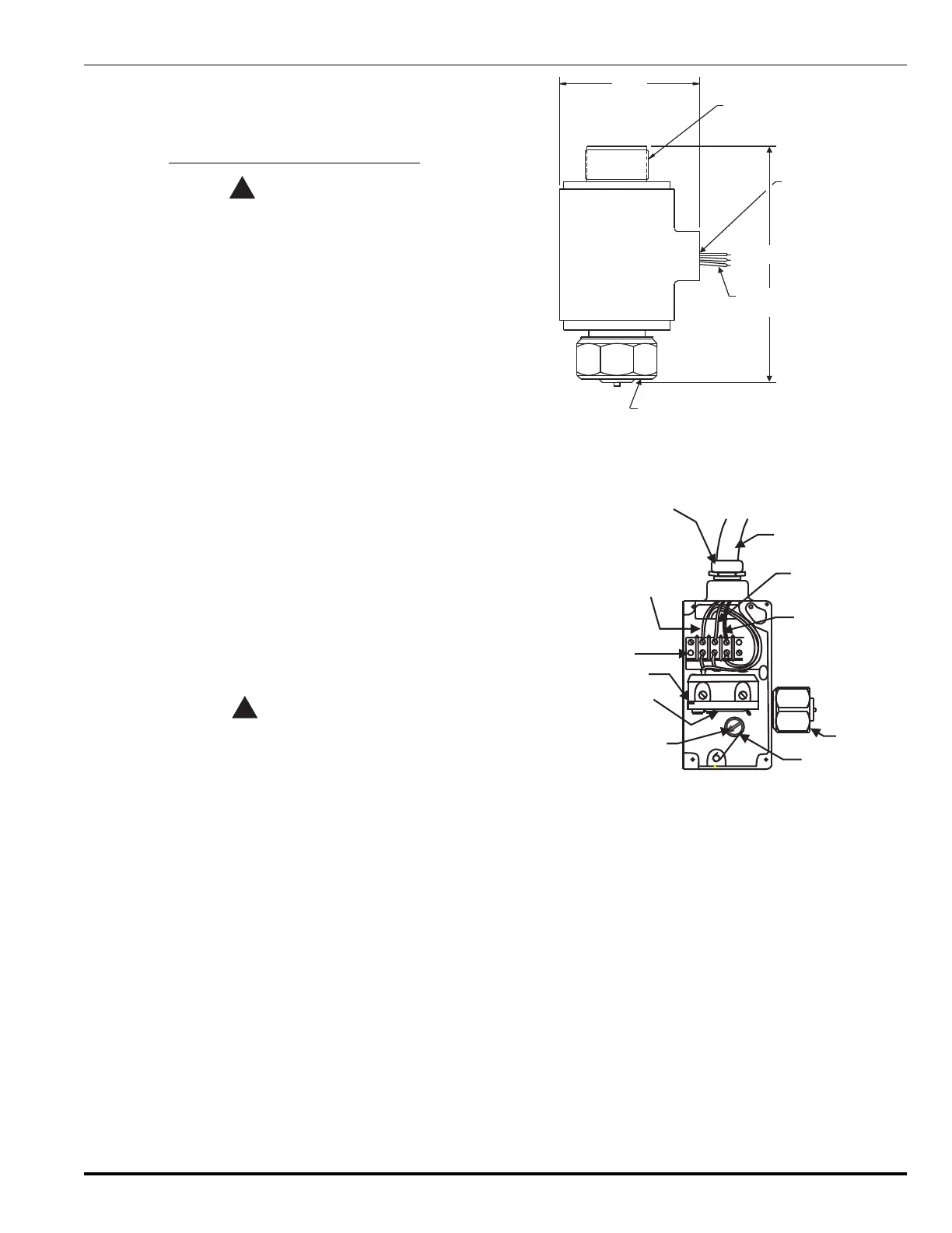
5.28"
2.90”
1.25-18 UNEF-2A
CONNECTION
1/2"-14 NPT
CONDUIT
CONNECTION
(3) 18 AWG-LEADS
18” (457.2 mm) LONG
SWIVEL NUT
1.25-18UNEF-2B
CONNECTION
(76.33 mm)
(134.11 mm)
Figure 4-14. Installation of Electric Control Head
(Stackable Type), P/N 486500-01
3
0.750 NPT TO FLEXIBLE
CONDUIT ADAPTER
PLUS OR HOT CONNECTION
(TERMINAL 3)
TERMINAL STRAP
MICROSWITCH
MICROSWITCH
LEVER
INDICATOR AND
RESET STEM
CAM
SWIVEL
NUT
MINUS, NEUTRAL
OR GROUND CONNECTION
(TERMINAL 1)
OPTIONAL CONNECTION
FOR MICROSWITCH
(TERMINAL 2)
FLEXIBLE CONDUIT
2
Figure 4-15. Electrical Connections for Control Head,
P/Ns 890181, 895630 and 890149
 Loading...