4-18
90-FM200M-000 September 2004
FM-200
®
ECS Series Engineered Fire Suppression Systems
4-3.10.2 MULTIPLE CYLINDER SYSTEM
WARNING
!
Cylinders must be located and mounted
where they will not be accidently damaged or
moved. If necessary, install suitable
protection to prevent the cylinder from
damage or movement.
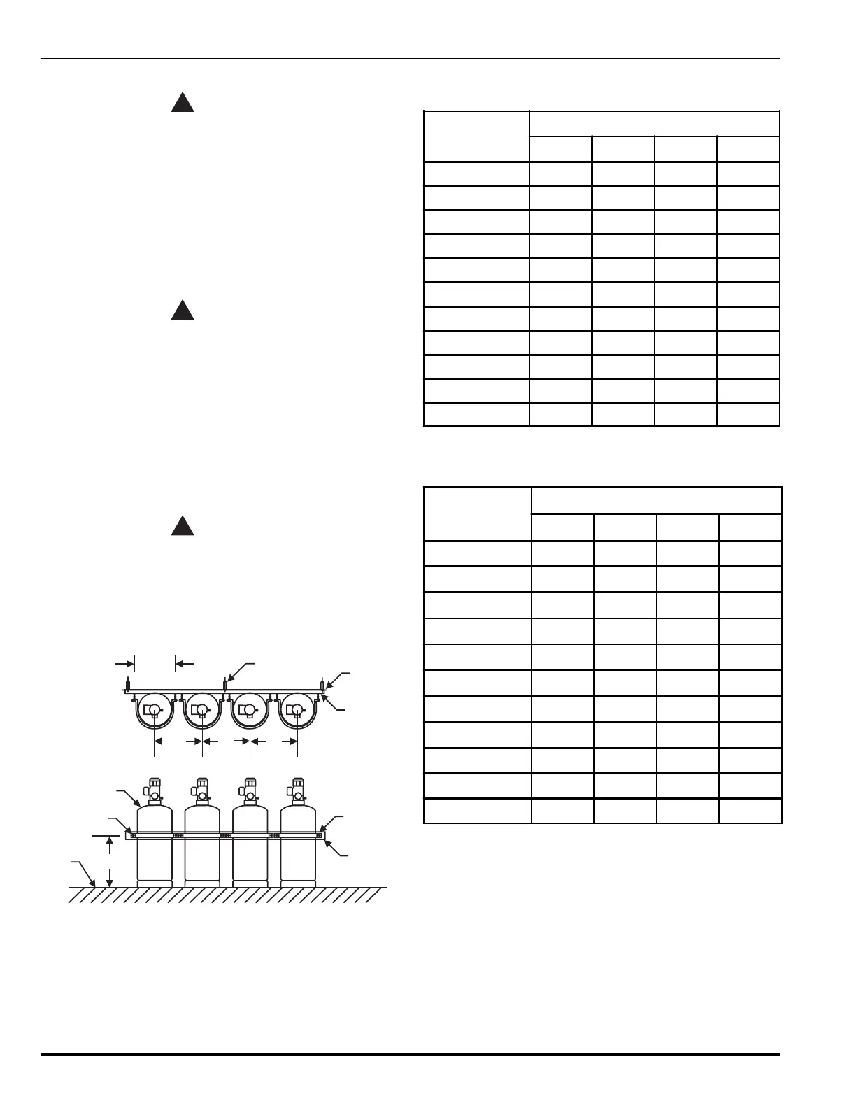
1. Position the cylinders in the designated location and
secure them in place with cylinder straps and attach-
ing hardware (see Figure 4-13 and Tables 4-13 and
4-14). Orient the cylinders so that the valve outlets are
angled towards the El-check valves in the manifold.
WARNING
!
The discharge hose must be connected into
the system piping before attaching it to the
cylinder valve.
2. Remove the safety cap from one cylinder outlet port
and connect the flexible discharge hose to the cylinder
outlet port. Repeat for each cylinder in the system.
3. Remove the protection caps from the cylinder
actuation ports.
4. Install the control heads on the cylinder valve
actuation ports.
WARNING
!
Control heads must be in the SET position (that
is, the actuating pin must be in the fully
retracted or SET position) before attaching to
FM-200 cylinders in order to prevent accidental
discharge. Personal injury and/or property
damage could occur.
A
(TYP)
ANCHOR AND STUD (TYP)
WALL
FRAMING
CYLINDER
SUPPORT
CYLINDER
STRAP
VERSABAR
FLOOR
LEVEL
C
(BOLT SIZE)
CYLINDER
(TYP)
BBB
D
Figure 4-13. Multiple Cylinder Installation, Vertical
Mounting (see Tables 4-13 and 4-14 for dimensions)
Table 4-13. Multiple Cylinder Installation Dimensions,
Inches
Cylinder
Part Number
Dimensions
ABCD
90-10001X-001 8.52" 11.00" 3/8" 7.38"
90-10002X-001 8.52" 11.00" 3/8" 12.50"
90-10004X-001 10.69" 13.00" 3/8" 10.63"
90-10007X-001 10.69" 13.00" 3/8" 20.00"
90-100125-001 14.56" 18.00" 9/16" 20.88"
90-10020X-001 15.44" 18.00" 9/16" 29.63"
90-10020X-101 14.56" 18.00" 9/16" 29.63"
90-10035X-001 17.88" 21.00" 9/16" 37.13"
90-10060X-001 24.12" 27.00" 9/16" 34.00"
90-10060X-100 25.75" 27.00" 9/16" 38.50"
90-10090X-001 25.75" 30.00" 9/16" 48.50"
Table 4-14. Multiple Cylinder Installation Dimensions,
Millimeters
Cylinder
Part Number
Dimensions
ABCD
90-10001X-001 216 mm 279 mm 10 mm 187 mm
90-10002X-001 216 mm 279 mm 10 mm 318 mm
90-10004X-001 272 mm 330 mm 10 mm 270 mm
90-10007X-001 272 mm 330 mm 10 mm 699 mm
90-100125-001 370 mm 457 mm 14 mm 597 mm
90-10020X-001 392 mm 457 mm 14 mm 991 mm
90-10020X-101 370 mm 457 mm 14 mm 991 mm
90-10035X-001 454 mm 533 mm 14 mm 1118 mm
90-10060X-001 613 mm 686 mm 14 mm 978 mm
90-10060X-100 654 mm 686 mm 14 mm 978 mm
90-10090X-001 704 mm 762 mm 14 mm 1232 mm
 Loading...