4-22
90-FM200M-000 September 2004
FM-200
®
ECS Series Engineered Fire Suppression Systems
4-3.18 Installation of Pressure Trip, P/N 874290
Install the pressure trip on the discharge manifold or piping
in the horizontal position as shown on the system draw-
ings. Connect the trip to the piping with 1/2-inch Schedule
40 pipe. The minimum operating pressure required is
75 PSIG (5.17 bar gauge). The maximum allowable load to
be attached to the retaining ring is 100 lb. (45.4 kg).
4-3.19 Installation of Manual Pull Station,
P/N 871403
1. Locate the remote pull boxes as shown on the system
installation drawings.
2. Connect the pull boxes to the control heads using 3/8-
inch, Schedule 40 pipe. Do not run more than one cable
in each pipe run.
3. Install a corner pulley at each change in pipe direction.
Do not bend the pipe. A dual-pull equalizer (P/N 840051)
should be installed where one pull box operates two
controls. A dual pull mechanism (P/N 840058) should
be installed where two pull boxes operate one control.
4. Beginning at the pull boxes, remove the covers of
the first corner pulley. Feed the cable through the
pulley into the 3/8-inch pipe. Connect one end of the
cable to the cable fastener in the pull box, allowing
the short end to project at least 1/2-inch. Seat the
cable in the groove by pulling on the long end. Screw
the fastener and cable into the handle. Route the
other end to the control heads, taking up as much
slack as possible. Attach the end of the cable to the
fastener in the control head.
5. Reattach the corner pulley covers.
6. Check that control head is in SET position. Install the
control head to the FM-200 cylinder valve.
4-3.20 Installation of Discharge Indicator,
P/N 875553
The discharge indicator must be installed on the discharge
manifold, either in a vertical or horizontal position. The indi-
cator has a 3/4-inch NPT male connection. Make certain
the indicator stem is in the normal position.
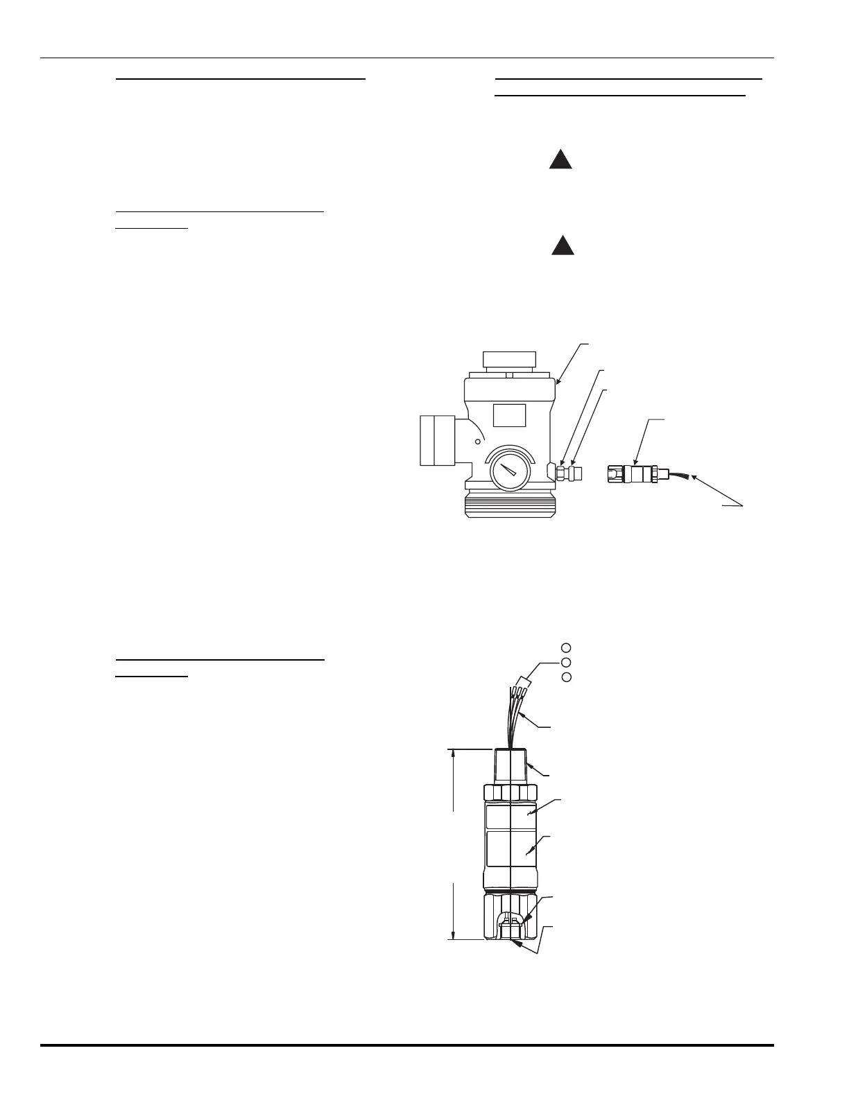
4-3.21 Installation of Supervisory Pressure Switch,
P/Ns 06-118262-001 and 06-118263-001
Installation of the supervisory pressure switch can be ac-
complished safely on a pressurized cylinder.
WARNING
!
Before installing the pressure switch,
de-energize all electrical components to
prevent injury.
CAUTION
!
When attaching or removing the supervisory
pressure switch from the cylinder valve, attach
a wrench to the fitting and hold securely while
tightening or loosening the pressure switch.
VALVE
WRENCH FLATS
SUPERVISORY PRESSURE
SWITCH FITTING
PRESSURE SWITCH
ELECTRICAL CABLE
FOR SWITCH CONNECTION
Figure 4-18. Installation of Supervisory
Pressure Switch (Up to 2½" Valve)
Note: The control panel must be UL Listed and/or
FM Approved for releasing device service and com-
patible with Kidde FM-200 equipment.
NAMEPLATE LABEL
0.500 -14 NPT
FACTORY SEALED
LEADWIRES 36" LONG ± 1”
CAUTION LABEL
O-RING
0.250" SAE 45° FLARE
(CONNECTION FOR
06-118262-001
SHOWN)
3
2
1
BLUE: N.O. (N.C. UNDER PRESSURE)
BLACK: N.C. (N.O. UNDER PRESSURE)
VIOLET: COM.
4.125”
(10.48 cm)
Figure 4-19. Supervisory Pressure Switch
Electrical Connections
 Loading...