4-23
September 2004 90-FM200M-000
FM-200
®
ECS Series Engineered Fire Suppression Systems
P
213
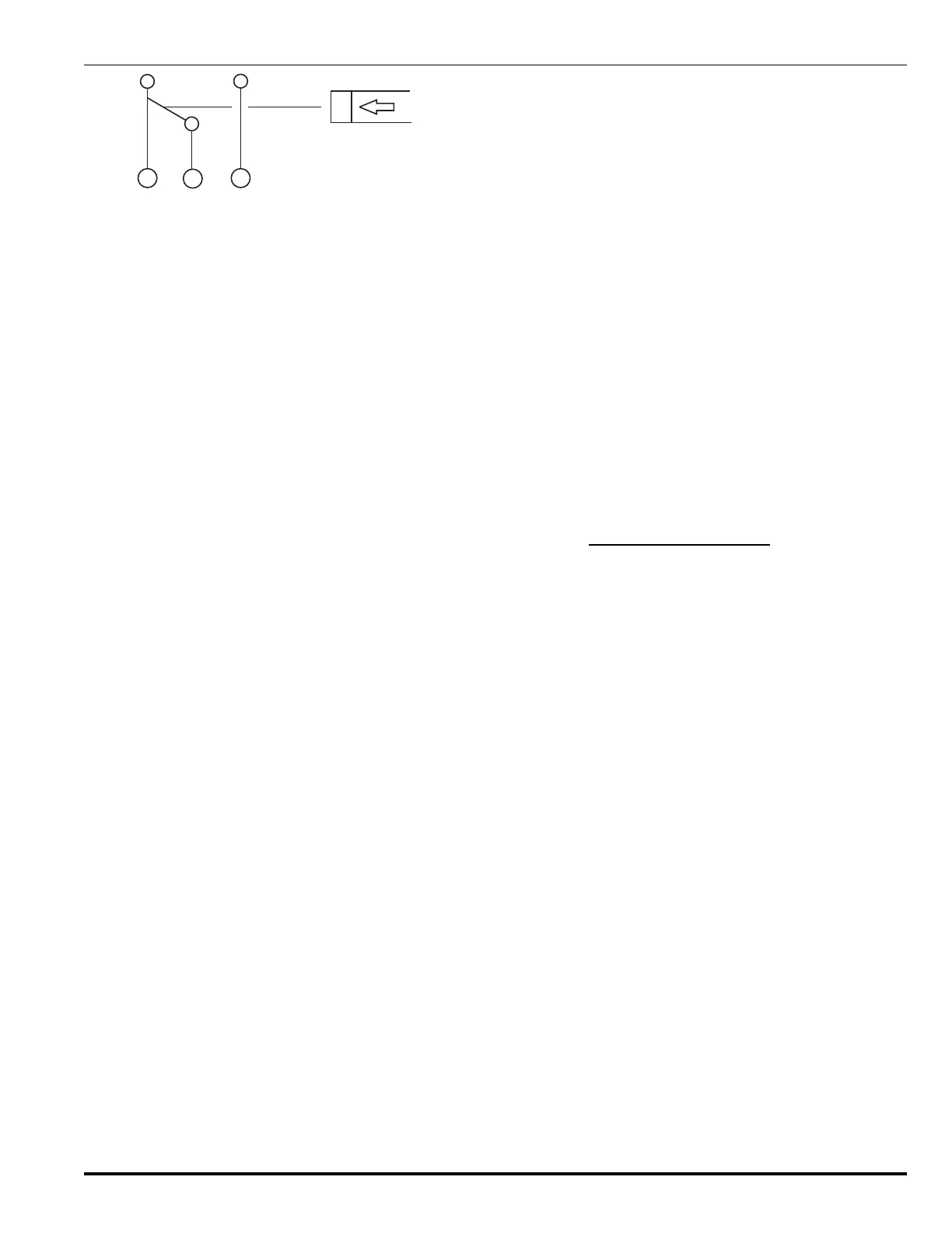
• 5A 24 Vdc (Resistive)
• 5A 240 Vac (Resistive)
Figure 4-20. Supervisory Pressure Switch
Connection Diagram and Electrical Rating
Note: When cylinder supervisory pressure switch
(P/N 06-11826X-001) is connected to a supervised
control panel circuit, and the switch is wired NC
under pressure, it is not possible to distinguish
between a wiring fault and a loss of container pres-
sure. This configuration should only be used if ac-
cepted by the Authority Having Jurisdiction.
4-3.21.1 INSTALLATION OF PRESSURE SWITCH
06-118262-001
Install the pressure switch as follows:
Note: Do not use with 3" valves.
1. Check that the sealing surface of the flare connection
of the supervisory switch is not scratched, dented,
scored, etc.
2. Remove the end cap from the pressure switch port of
the valve. This is a flare fitting and does not require
tape dope or any type of sealant.
3. Install the pressure switch onto the pressure port of
the valve. Be sure to secure the pressure port with a
wrench so that you are not turning the port fitting fur-
ther into the valve. Tighten the switch hand-tight and
then tighten 1/4-turn further using a wrench.
4. Important: Leak test the pressure switch connection
with an FM-200 leak detector or a bubbling solution. If
the connection leaks, the switch may be tightened fur-
ther until the leak is eliminated, again, be sure to have
a counter wrench on the switch port.
4-3.21.2 INSTALLATION OF PRESSURE SWITCH
06-118263-001
Install the pressure switch as follows:
Note: For 3" valves only.
1. Hold the pressure switch fitting on the valve with a
wrench and remove the 1/8-inch plug with a second
wrench. Ensure that the fitting does not rotate in the
valve body. The fitting contains a check valve that will
prevent the escape of the cylinder contents.
2. Before fitting the switch, apply Permacel
®
No. 412D
Te f lo n
®
tape to the male threads of the pressure switch.
3. Install the pressure switch into the port of the valve. Be
sure to secure the pressure port fitting with a wrench.
Tighten the switch hand-tight and then tighten 1¼-turns
further using a wrench.
4. Important: Leak test the pressure switch connection
with an FM-200 leak detector or a bubbling solution. If
the connection leaks, the switch may be tightened fur-
ther a 1/4-inch turn at a time until the leak is eliminated,
again, be sure to have a counter wrench on the switch
port. Do not exceed two turns from hand-tight. Refer to
ANSI B1.20.3 for NPT thread engagement details.
4-3.22 Post-Installation Checkout
After an FM-200 system installation has been completed,
perform the following inspections and tests.
1. Verify that the cylinders of correct weight and pressure
are installed in accordance with installation drawings.
2. Verify that the cylinder brackets and straps are properly
installed and all fittings are tight.
3. The piping distribution system must be inspected for
compliance with the system drawings, NFPA 2001, de-
sign limitations within this manual and the computer-
ized hydraulic calculations associated with each
independent piping and nozzle configuration.
4. Check that the discharge manifold, discharge piping and
actuation piping are securely hung. Ensure all fittings
are tight and securely fastened to prevent agent leak-
age and hazardous movement during discharge. The
means of pipe size reduction and installation position of
the tees must be checked for conformance to the de-
sign requirements.
5. The piping distribution system must be cleaned, blown
free of foreign material and inspected internally to en-
sure that oil or particulate matter will not soil the hazard
area or reduce the nozzle orifice area and affect agent
distribution.
6. System piping should be pressure tested in accordance
with the requirements of NFPA 2001.
 Loading...