6-1090-FM200M-000 September 2004
FM-200
®
ECS Series Engineered Fire Suppression Systems
6-4.3 Nitrogen Cylinder Recharge
Nitrogen cylinders must be recharged when the cylinder
pressure gauge indicates pressure is below normal (1800
PSIG at 70°F [124 bar gauge at 21°C] or as adjusted for
temperature) or immediately after discharge. Nitrogen used
for charging must comply with Federal Specification
BB-N-411C, Grade A, Type 1. Copies of this specification
may be obtained from: Global Engineering Documents,
2625 S. Hickory St., Santa Ana, CA 92707.
WARNING
!
Before recharging, the cylinder must be firmly
secured by chains, clamps or other devices to
an immovable object such as a wall, structural
I-beam or permanently mounted holding rack.
Recharge the nitrogen cylinders as follows:
1. Remove the protection cap from the cylinder valve ac-
tuation port.
2. Install the nitrogen cylinder recharge adapter
(P/N 933537) to the cylinder valve actuation port and
plug valve outlet port with 1/8" NPT pipe plug.
3. Connect the nitrogen recharging supply hose to the
adapter. Tighten securely.
4. Open the nitrogen recharging control valve slowly until
full nitrogen flow is obtained.
5. Monitor the recharging supply pressure gauge. Close
the charging control valve when the gauge indicates
the proper cylinder pressure (1800 PSIG at 70°F
[124 bar gauge at 21°C]).
6. Allow the cylinder to cool to ambient temperature and
recheck the nitrogen cylinder pressure.
7. Open the valve and add additional nitrogen as neces-
sary to obtain a full cylinder charge at ambient tem-
perature (1800 PSIG at 70°F [124 bar gauge at 21°C]).
Refer to Figure 6-5.
8. Close the valve and remove the supply hose and charg-
ing adapter from the nitrogen cylinder.
9. Using a soap solution, thoroughly check the nitrogen
cylinder valve for leakage. Bubbles in the soap solu-
tion indicate leakage and shall be cause for rejection
of the cylinder.
10. At the completion of the leak test, thoroughly clean and
dry the cylinder valve.
11. Ensure the cylinder valve control head port is clean
and dry.
12. Immediately install the protective cap to the actuation
port of the cylinder valve.
13. Install the charged cylinder as described below.
6-4.4 Nitrogen Cylinder Installation
1. Install the nitrogen cylinder in position in the mount-
ing bracket.
2. Tighten sufficiently to hold cylinder in place while al-
lowing cylinder enough free play to be manually rotated.
3. Turn the cylinder until the cylinder valve discharge out-
let is in the desired position.
CAUTION
!
The nitrogen cylinder must be positioned so
that the control head, when installed, is readily
accessible and cannot be obstructed during
manual operation.
4. Securely tighten the mounting bracket clamps
and hardware.
5. Remove the pipe plug, reconnect the adapter
(P/N 6992-0501) and flexible actuation hose or tubing
to the cylinder valve outlet port.
6. Remove the protective cap from the cylinder valve
actuation port.
WARNING
!
Ensure the control head is in the SET position
(that is, the actuating pin is in the fully retracted
or SET position). Failure to do so will cause
the nitrogen cylinder to discharge when the
control head is installed.
7. Install the control head to the cylinder valve and
tighten securely.
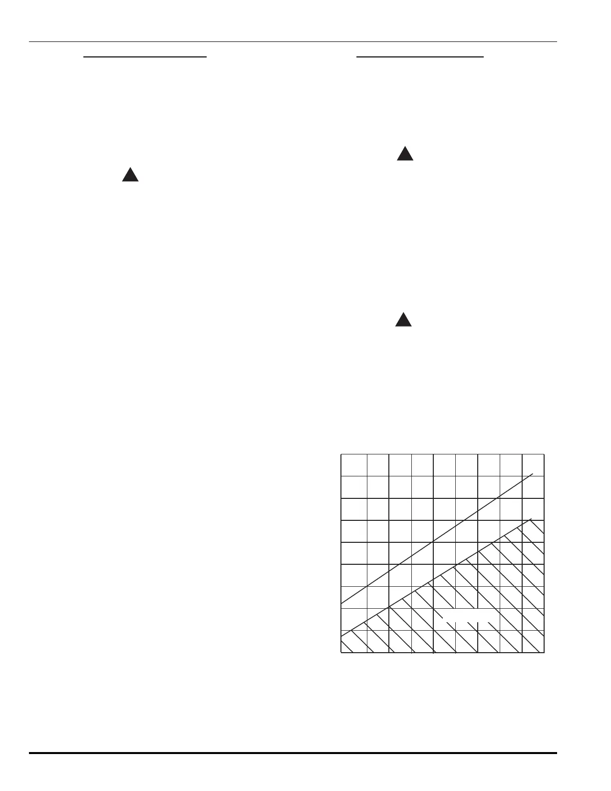
TEMPERATURE °F
N PRESSURE - TEMPERATURE CHART
2
PRESSURE PSIG
-40° 40° 60°-20° -20°0° 80° 100° 120° 140°
1200
1300
1400
1500
1600
1700
1800
1900
2000
2100
RECHARGE
NOMINAL PRESSURE
MINIMUM ALLOWABLE PRESSURE
Figure 6-7. Nitrogen Temperature vs. Pressure Data
 Loading...