4 / 6 P/N 3101069-EN • REV 005 • ISS 19OCT20
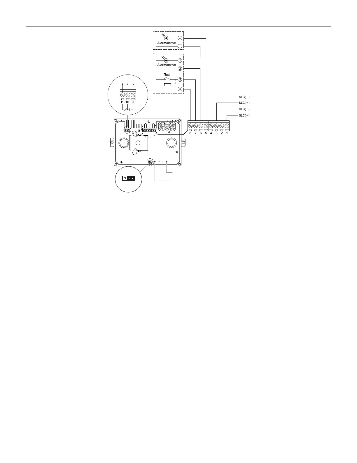
Figure 6: Duct detector wiring
(1) Auxiliary equipment. Power-limited unless connected to a
nonpower-limited source. If the source is nonpower-limited,
eliminate the power-limited mark and maintain a minimum of
0.25 in. (6.4 mm) space from power-limited wiring. For other
mounting methods, see enclosure and bracket installation sheets
to maintain separation of power-limited and nonpower-limited
wiring. The wire size must be capable of handling fault current from
the nonpower-limited source.
— or —
Use type FPL, FPLR, FPLP, or permitted substitute cables,
ensuring that the power-
limited cable conductors extending beyond
the jacket are separated by a minimum of 0.25 in. (6.4 mm) space
or by a nonconductive sleeve or nonconductive barrier from all
other conductors. The wire size must be capable of handling fault
current from the nonpower-limited source. Refer to NFPA 70 for
more details.
(2) Remote alarm/active indicator. See “Specifications” on page 5 for a
list of available model numbers.
Connect only one remote test station or LED indicator to the
detector. Wiring is unsupervised. Maximum wire resistance is 10
per wire.
Remote test station. See “Specifications” on page 5 for a list of
available model numbers.
Power indicator.
Alarm Indicator.
JP3 (shown in the factory default position, for supervisory mode).
Alarm position.
Supervisory position.
Testing
Verifying the air pressure differential
In order to verify air pressure differential, air must be moving through
the HVAC system.
To verify the air pressure differential:
1. Connect a suitable air pressure differential meter to the sampling
tube and exhaust tube openings as shown in Figure 7.
2. Verify that the air pressure differential reading falls within the
specified operating range of the detector. See “Specifications” on
page 5.
3. If the air pressure differential measured does not fall within the
specified operating range of the detector, make sure the sampling
tube air holes are not obstructed and are facing the HVAC system
airflow.
(1)
(5)
(6)
(2) (3)
(3) (4)
JP3
(7)
(8) (9)