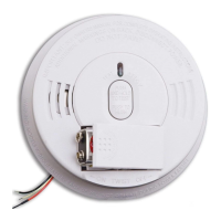
4. Connect brown cable from connector plug of smoke alarm to live (red
or brown) mains power cable .
5. If interconnection is desired, connect orange or white cable from con-
nector to interconnect strand on the 3 core & earth cable. See section,
“Interconnecting Smoke Alarms.”
NOTE: If this will be a single-station smoke alarm, cover orange or white
cable with electrical tape and tuck into pattress.
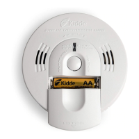
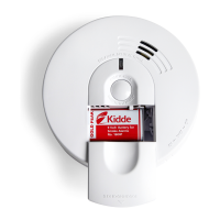
Steps 6-9 for Models KF1 and KF2 ONLY:
6. Lift open battery pocket door.
7. Connect new 9-volt battery to battery connector inside battery pocket. BE
SURE BATTERY IS SECURELY CONNECTED. Smoke alarm may beep
briefly when battery is installed.
8. Close battery pocket door, snapping it into place.
9. Push button and hold button on front cover of smoke alarm for three
(3) seconds. Smoke alarm should sound its alarm horn if battery is fit-
ted correctly.
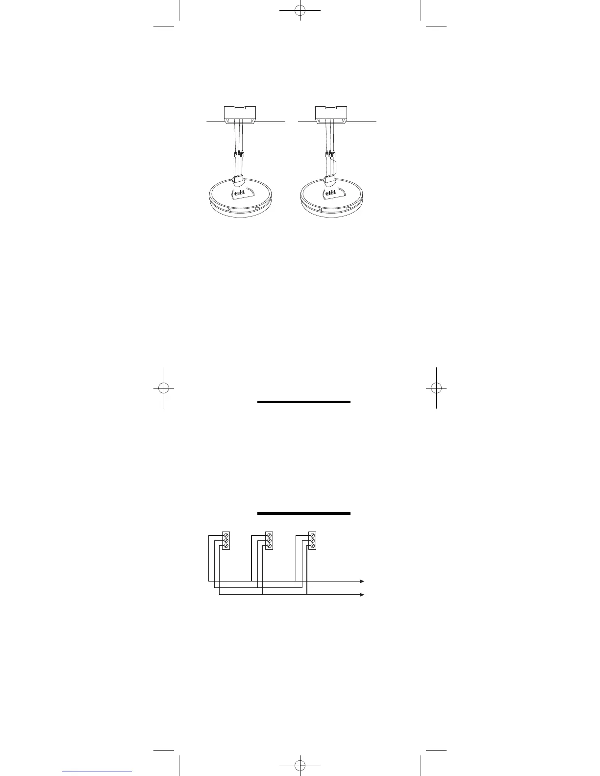
10. Attach connector plug to pins on back of smoke alarm. Plug will only
fit one way and will snap into place.
11. Gently tug connector to be sure it is attached securely.
12. Position smoke alarm to mounting plate so that keyslot on side of
smoke alarm is to left of tab on mounting plate. Turn clockwise to lock
into
place.
NOTE: (For Models KF1 and KF2 only):
Smoke alarm will not mount to plate if battery is not installed.
13. Turn on power at main fuse box or circuit breaker. The green LED on the
cover should be illuminated.
14. Test smoke alarm. See “TESTING THE SMOKE ALARM”.
INTERCONNECTING
SMOKE ALARMS
•
Use 1.5mm
2
minimum solid or stranded cable with a rating of 230V.
When interconnecting, maximum cable length between any two is 450
m for 1.5mm
2
or 1200 m for 2.5mm
2
(20 OHMS loop resistance).
•
NOTE: Maximum length under BS7671 17th Edition wiring regs
amendment 1 for CB/RCBO type B is 72 metres for TN-S or TN-C-S
systems (source "On-Site Guide" page 59)
•
This smoke alarm may be interconnected with as many as 23other
Models KF1, KF1R, KF2 and KF2R smoke alarms. DO NOT connect to
any other type or model smoke alarm.
•
Connect smoke alarms to a single circuit. Wiring must conform to IEE
Regulations for electrical installation.
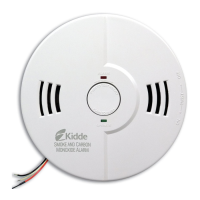
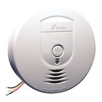
RED AND GREEN LED
INDICATORS
This smoke alarm features red and green LED indicators that can be seen
through the Push-to-Test button or the LED lens above the test button.
The LEDs indicate the following:
GREEN LED
ON —
AC power is present.
OFF —
AC power is not present.
RED LED
Blinks once a minute — indicating normal operation.
Blinks once a second — smoke alarm senses smoke and simulta-
neously sounds an audible alarm.
Blinks once every 10 seconds — smoke alarm is quieting an unwanted
alarm. (Models KF1, KF1R, KF2 and
KF2R)
(Interconnected system only):
4