Do you have a question about the Kieback&Peter RBW301-C and is the answer not in the manual?
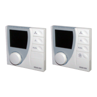
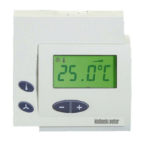
Description of the RBW30x-C module with display, sensor, and setpoint adjustment capabilities.
Details the intended use and compatible systems for the room control module.
Essential guidelines for safe installation, commissioning, and use of the RBW30x-C module.
Explanation of warning symbols (Warning, Caution) indicating risk levels and potential consequences.
Instructions for proper disposal of the product as electronic waste, adhering to local regulations.
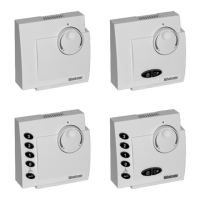
Details on RBW301-C to RBW305-C variants, including electrical, environmental, and operational specs.
Covers interfaces, measurement range, accuracy, housing, protection, dimensions, and weight.
Details on the Z146 adapter frame for direct wall mounting.
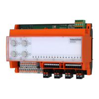
Lists compatible room controllers and automation stations for RBW30x-C module integration.
Technical drawings showing the precise dimensions of the RBW30x-C module and Z146 adapter.
Illustrations showing connection examples for DDC420, RCN420-B, and RCC200-L systems.
Guidance on choosing an optimal location for accurate room temperature measurement.
Step-by-step guide for mounting the RBW30x-C on a flush-mounted box using RJ9 connector.
Step-by-step guide for mounting the RBW30x-C on a flush-mounted box using 4-wire terminals.
Instructions for direct wall mounting using the Z146 adapter frame.
Explanation of the knob and button functions for setting temperature, fan, and presence modes.
Interpretation of various symbols shown on the display for status, heating, cooling, and time.
Procedure for adjusting the room temperature setpoint using the knob and display.
How to activate/deactivate energy saving mode using the presence button (RBW304-x, RBW305-x).
Instructions for setting, deleting, and managing timed schedules for room utilization.
How to temporarily extend room utilization time using the presence button.
Procedure for setting the current time and date on the RBW30x-C module.
Guidelines for setting the CAN bus address switch for different system configurations.
Procedure for online installation using a magnet to trigger the service PIN.
Explanation of service-related indicators like heating/cooling valve, error codes, and version numbers.
Steps to query service settings, enter PIN, and check valve outputs.
| Power consumption | 2.5 W |
|---|---|
| Operating temperature | -10 °C to +50 °C |
| Protection class | IP40 |
| Supply voltage | 24 V DC |
| Input voltage | 24 V DC |
| Storage temperature | -20 °C to +70 °C |
| Weight | 240 g |