EasyManua.ls Logo

Kilsen KAL790 User Manual

Kilsen KAL790
20 pages
To Next Page IconTo Next Page
Page #1 background imageLoading...
Page #1 background image
© 2020 Carrier. All rights reserved. 1 / 20 P/N 10-5151-501-101-02 • ISS 15JUN20
KAL790 Addressable Retention Module
Installation Sheet
EN ES IT PT FR NL CS NO PL HU
1
EN: Installation instructions
Description
The KAL790 provides a remote input and a potential-free
voltage relay output to an addressable fire detection system.
The input signal is constantly monitored and its status
communicated to the fire panel. The output is fail-to-safe.
Auxiliary supply monitoring is also included.
The output has three positions: common (C), normally open
(NO) and normally closed (NC). In standby the C and NC
contacts are connected. When the output is activated the C
contact is connected to the NO contact.
The input is polarity insensitive. When electrical contacts are
not connected, the module remains in standby mode.
Note: The input state is latched (this is not configurable) and
returns to standby after a system reset.
The module may be used with any device and the choice of
contact used (C, NC or NO) will set the desired event.
Installation
Caution: For general guidelines on system planning, design,
installation, commissioning, use and maintenance, refer to the
EN 54:14 standard and local regulations.
Module installation
Disconnect the fire system power supply and install the module
in the protective housing provided.
Connect the loop cable shield wire to the earth screw.
Question and Answer IconNeed help?

Do you have a question about the Kilsen KAL790 and is the answer not in the manual?

Kilsen KAL790 Specifications

General IconGeneral
BrandKilsen
ModelKAL790
CategoryControl Unit
LanguageEnglish

Summary

Installation Instructions

Module Description

Details the module's remote input and potential-free voltage relay output for fire detection systems.

Module Installation

Instructions for disconnecting power, housing installation, and earth connection.

Module Connections and Setup

Connection Details

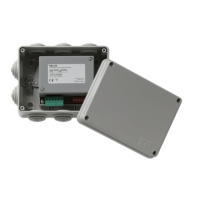
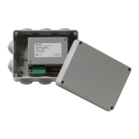
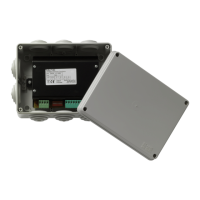
Overview of module connectors, DIP switch, and status LED as shown in Figure 1.

Loop Overloading Considerations

Guidance on verifying loop load capacity for large installations.

Power Supply Configuration

Instructions for setting module power supply via jumpers JMP1 and JMP2.

Addressing and Status LED

Details on setting module address using DIP switches and status LED configuration.

Maintenance and Testing

Guidelines for basic maintenance and yearly inspection of the module.

Specifications

Regulatory Information

Related product manuals