27
Introduction
Daily use
KIMAX2
Menu
Configuration
Calibration
Protecting
calibration
Electrical
installation
Sensor
installation
Additional
information
Standard installation truck—trailer
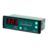
Kimax 2 in the cabin:
In a standard truck and trailer installation,
the brown wire is connected to the chassis
(- supply) and the black wire to +24 V
through switch and fuse.
The communication circuit is established by
connecting the white wire to the chassis
together with the brown wire and by routing
the red and green wire as a “new” wire from
the truck to the trailer.
This “new” wire is conducting both the
supply and communication for the sensor on
the trailer. The “new” supply through the
red wire, has a limited capacity of 200 mA
and must not be used for anything else than
Kimax 2 Sensor boxes.
Unused wires in the cable set are kept
insulated from the chassis and any other
conducting circuits.
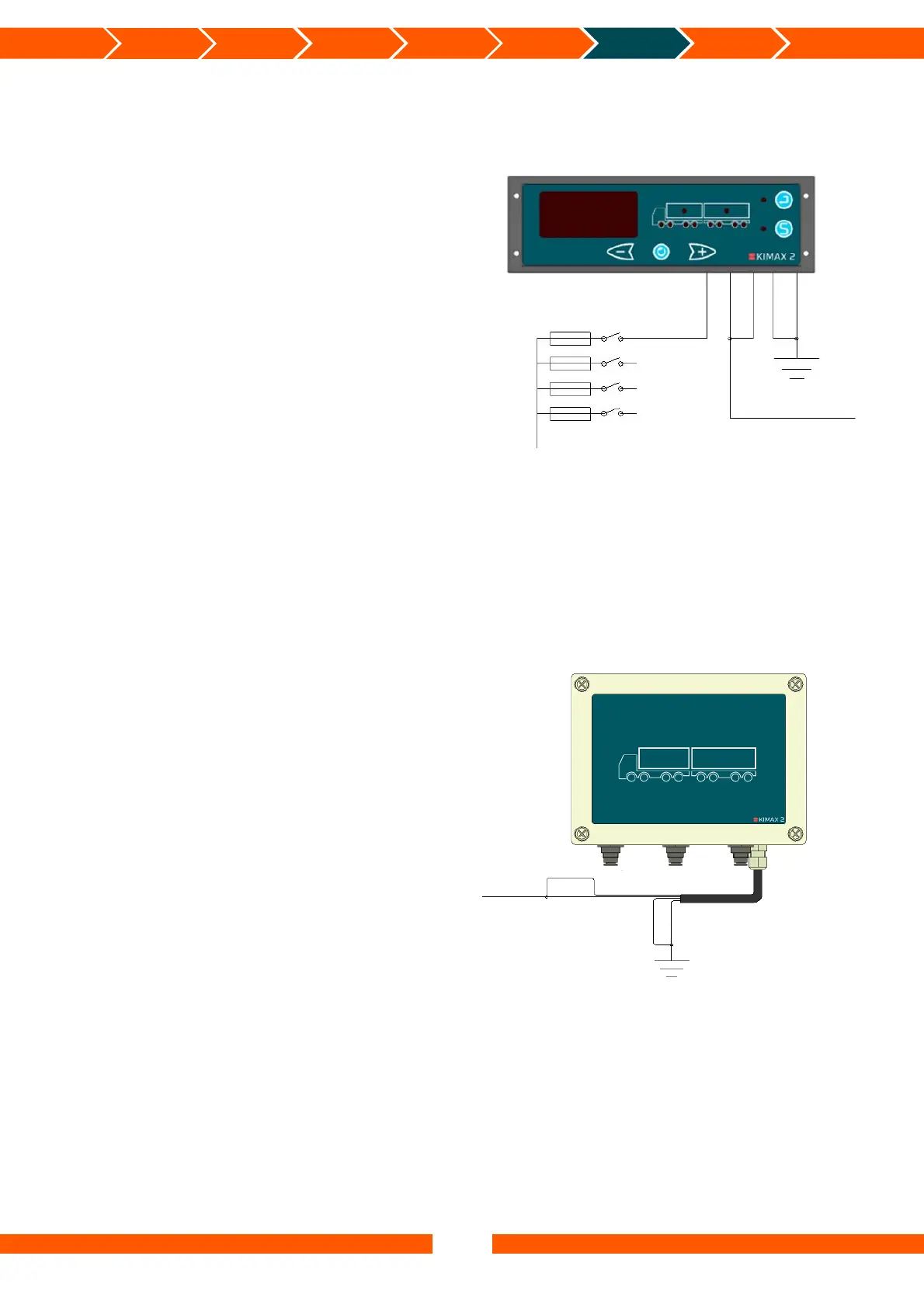
Kimax 2 on the trailer:
In a standard truck and trailer installation
the brown wire is connected to the chassis
(- supply) and the gray and green wire to
the “new” +24 V.
The communication circuit is established by
connecting the white wire to the chassis
together with the brown wire and by routing
the grey and green wire as a “new” wire
from the trailer to the truck.
This “new” wire is conducting both the
supply and communication for the sensor on
the trailer. The “new” supply through the
red wire, has a limited capacity of 200 mA
and must not be used for anything thing
else than Kimax 2 Sensor boxes.
Unused wires in the cable set are kept
insulated from the chassis and any other
conducting circuits.
24 V bus
Black
Fuse
Switch
Brown
Red
Green
White
Green
Grey
White
Brown
Supply and communication
for sensor on trailer
 Loading...