26
Introduction
Daily use
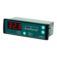
KIMAX2
Menu
Configuration
Calibration
Protecting
calibration
Electrical
installation
Sensor
installation
Additional
information
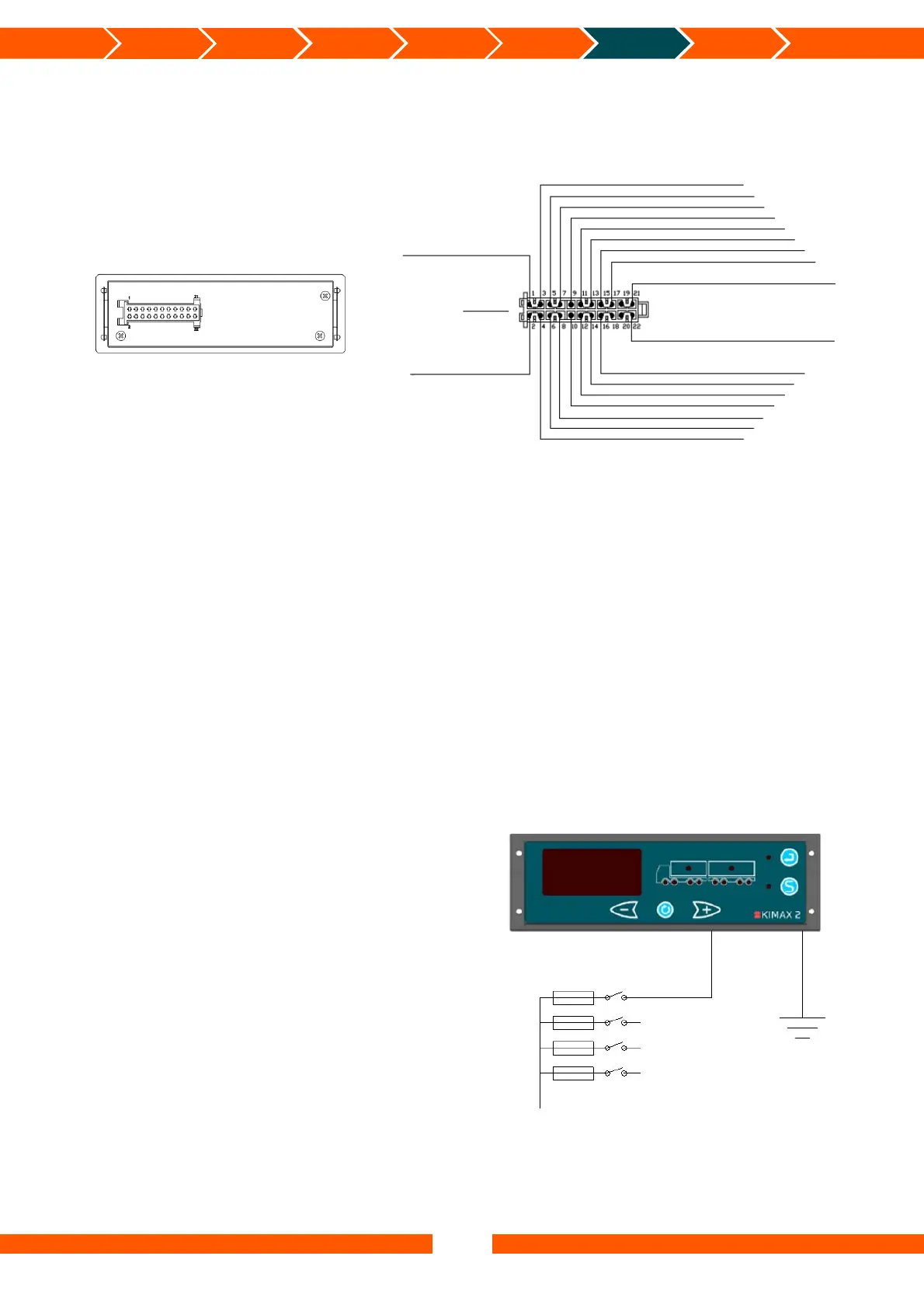
Electrical installation
The connections above marked with ‘*’ are only present if the connection is required by the
part number for a given instrument. This example is for a fully featured device.
Electrical connection
Always disconnect the battery before you perform any installation work on the system of the
vehicle.
Do not route the cables next to ignition cables or other cables carrying large currents.
Make sure that the cables are not exposed to tensile or shearing forces. Protect the cables with
rubber grommets if you route the cables through holes.
For connecting cables use crimp connectors or another approved method. Avoid short-
circuiting the system by faulty connections or squeezed cables.
Fasten the cables at suitable intervals.
Make sure all Kimax 2 instruments are protected by use of fuses in supply cables.
Basic installation
When you use your Kimax 2 Radio
instrument on a single vehicle, you only
need to connect the brown wire from pin 1
in the cable set to the chassis (- supply) and
the black wire from pin 2 to +24 V through
a switch (ignition) and a fuse and you are
done.
Unused wires in the cable set are kept
insulated from the chassis and any other
conducting circuits.
Rearside
Green – Communication I
White – Alarm 3 OC*
Orange – OBC
Red – sensor +10V*
Brown – sensor 0V*
White – sensor signal 1*
Blue – Alarm 4 OC*
Purple – Input (+24V)*
Green – CAN-LO (CAN-)*
White – CAN-HI (CAN+)*
Green – sensor signal 4*
Yellow – sensor signal 2*
Blue – sensor signal 3*
Red – Supply for sensorbox (filtered 10–30 V)
Yellow – Alarm 2 OC
Grey – Printer Tx
White – Communication II
10–30V
+Battery Black
-Battery Brown
STWS No 41035
Tyco No 929504-7
24 V bus
Black
Fuse Switch
Brown
 Loading...