34
Introduction
Daily use
KIMAX2
Menu
Configuration
Calibration
Protecting
calibration
Electrical
installation
Sensor
installation
Additional
information
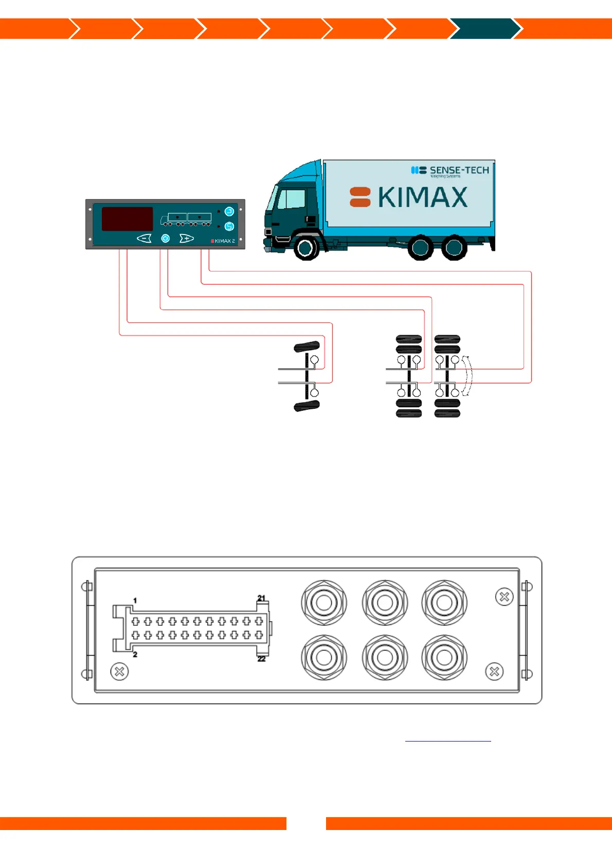
Air-sensor installation on your vehicle
When the suspension system is deviated in a left hand side and in a right hand side by use of a
level control valve in both left and right side, you can connect a Kimax instrument by using the
standard fittings you get together with your instrument according to the below diagram.
Basic layout
When your lift-axle is engaged, the pressure in air 3 left equals air 2 left and the pressure in
air 3 right equals air 2 right, axle 2 and 3 share the weight of the rear of your vehicle.
When your lift-axle is disengaged (lifted from the road) the pressure in air 3 right and air 3 left
is 0 bar and all the weight of the rear-end of your vehicle is carried and weighed by axle 2.
For additional layout options on different vehicle types please visit www.kimax.com.
Kimax 2 Radio
Air 3 left
Air 3 right
Air 2 left
Air 2 right
Air 1 left
Air 1 right
Air 1 right
Air 1 left
Air 2 right
Air 2 left
Air 3 right
Air 3 left
Lift - axle
Rearside
Air inlet 3 Air inlet 2
Air inlet 1
L
L
L
R
R
R
 Loading...