33
Introduction
Daily use
KIMAX2
Menu
Configuration
Calibration
Protecting
calibration
Electrical
installation
Sensor
installation
Additional
information
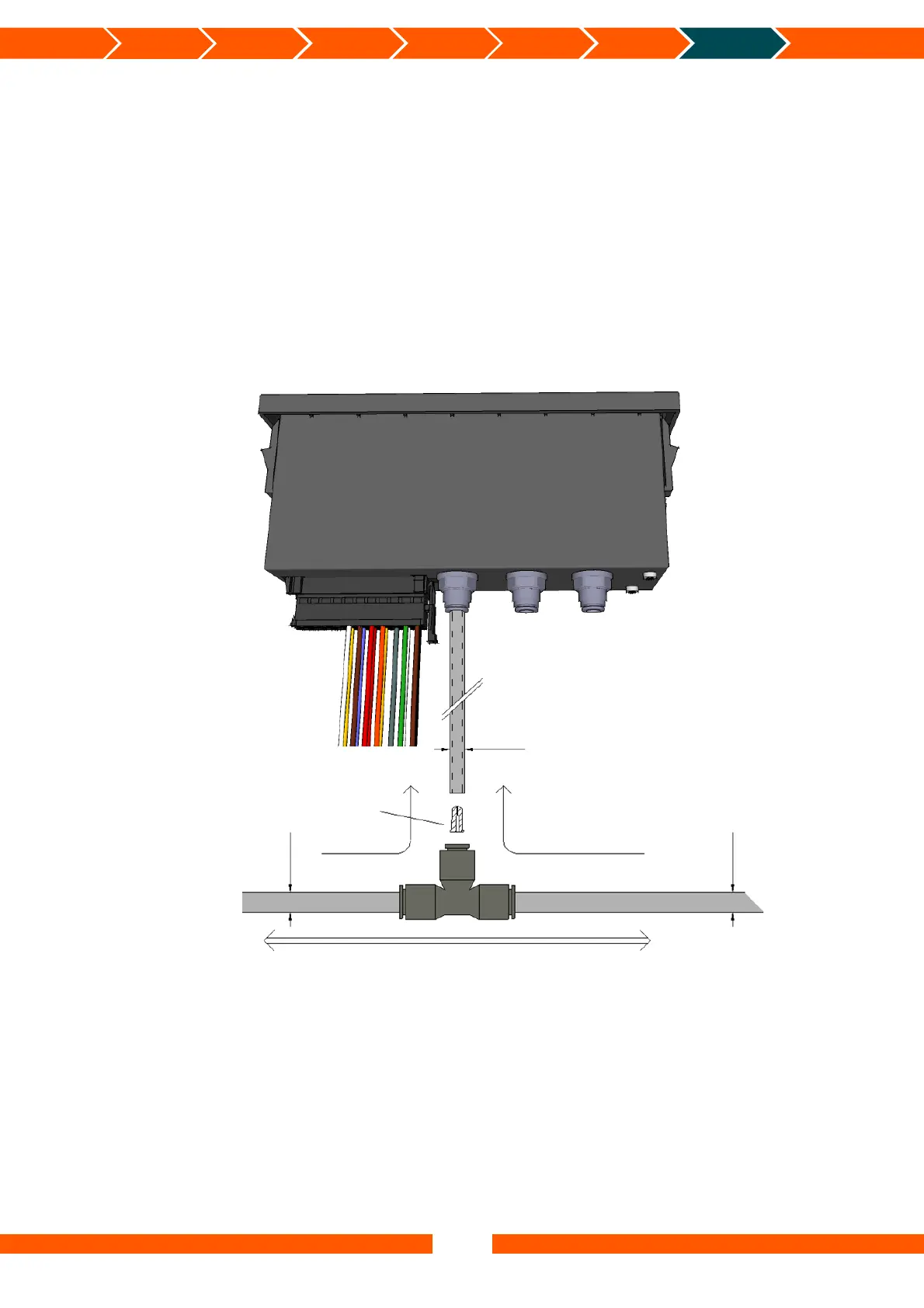
Cut the supply hose between the level valve and the bellow, assemble the hose again by using
a T-piece.
Connect the instrument to the air bellows by means of an approved Ø6 x 1 mm polyurethane
hose.
A throttle has to be put in every 6 mm hose at the T-piece end. It is important to mount the
throttle in T-piece end of the hose, it will not work i the correct way, when you put it in the
sensor end of the connecting hose.
The throttles protect the pressure sensors in the Kimax 2 instruments against burst-pressure.
Furthermore, the throttles protect the air circuit against unexpected leakage if one of the 6
mm hoses suffers damage.
Unexpected loss of compressed air may affect your breaking and steering capability.
All air-inlets on Kimax instruments and all belonging fittings are quick-release type.
You need to make a clean cut in a right angle with a sharp knife before you connect a new
tube to a Kimax instrument.
You can release the locking mechanism by push-in the releasing ring on the air-inlet.
(A 7 mm open-ended spanner is a suitable tool for pushing-in the release ring meanwhile you
slightly pull out the tube).
Throttle
8 mm*
6 mm
Air inlet 3
T-piece
Ma
or airflow to/from bellows
Air inlet 2
Air inlet 1
8 mm*
Minor airflow
towards pressure sensor
* De
endin
on the t
e of vehicle
 Loading...