40
Introduction
Daily use
KIMAX2
Menu
Configuration
Calibration
Protecting
calibration
Electrical
installation
Sensor
installation
Additional
information
Basic test setup
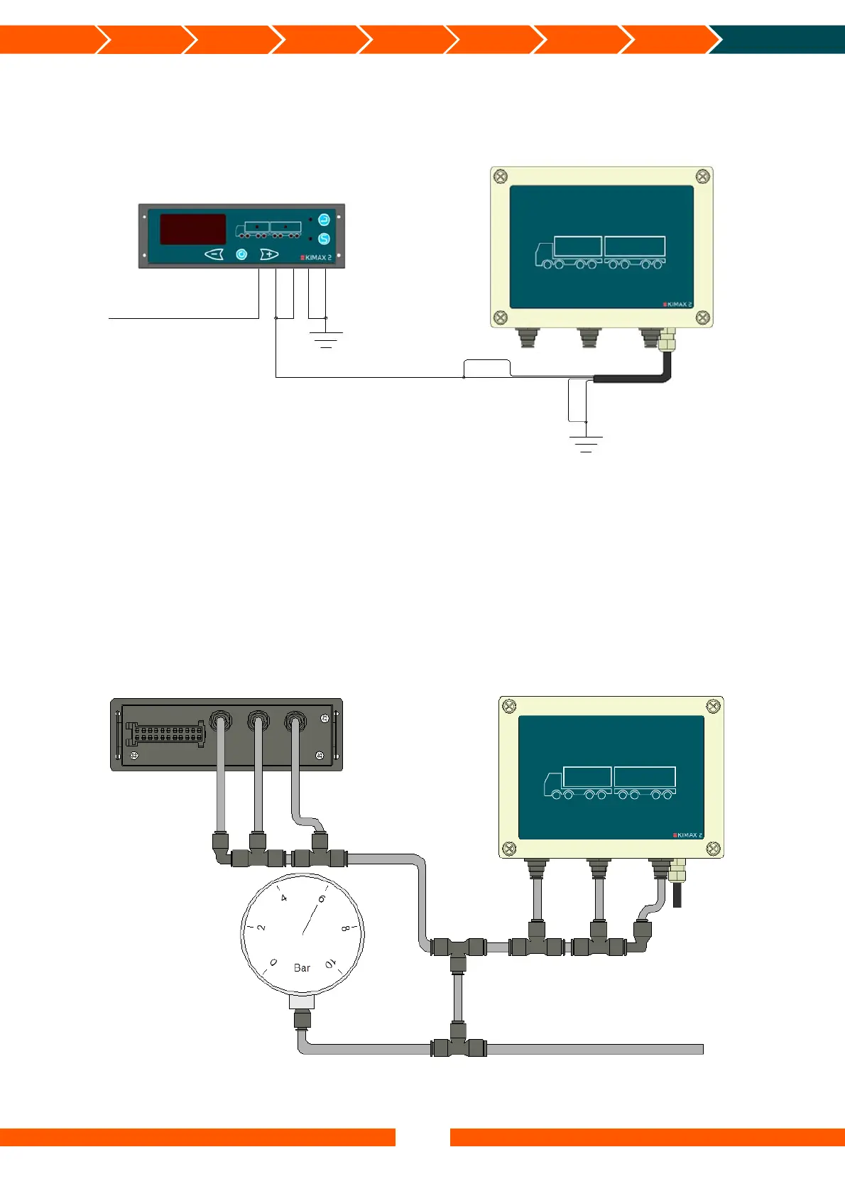
To test two instruments with air pressure sensors (e.g. 031110-01 and 051110-010) you can
connect them as shown here:
The instruments are configured as follows:
Kimax 2 Radio: HFA = 1, CH1 = LED1, CH2 = LED3 and CH3 = LED4.
Kimax 2 Sensor: HFA = 3, CH5 = LED5, CH6 = LED7 and CH7 = LED8.
All channels are LO-calibrated to 0,00 t when no pressure is applied to all the channels and HI-
calibrated to 10,0 t when 10 bar is applied to all the channels. Apply e.g. 6 bar to all channels
and you will get a total reading of 6 times 6,00 equal 36,0 on the display of the Kimax 2 Radio.
If you disconnect the white wire from ground, the communication between the two instruments
will stop and the reading on the Radio panel will be 3 times 6,00 equal 18,0. Connect the white
wire again and the reading will be 36,0 again. If the reading is not as expected, you may have
to recalibrate the instruments. See page 21.
Blac
10-30 V Supply
Brown
Red
Green
White
Green
Gre
White
Brown
Supply and communication
for sensor on traile
Adjustable air supply 0 - 10 bar
Air inlet 3
Air inlet 2
Air inlet 1
Air inlet 1
Air inlet 2
Air inlet 3


 To Next Page
 Loading...