SYSTEMS
Proper product installation, in accordance with these instructions, is the responsibility of the installing agent.
If you have any questions concerning these instructions, please call Kimball Customer Service.
Cetra
®
Assembly Instructions
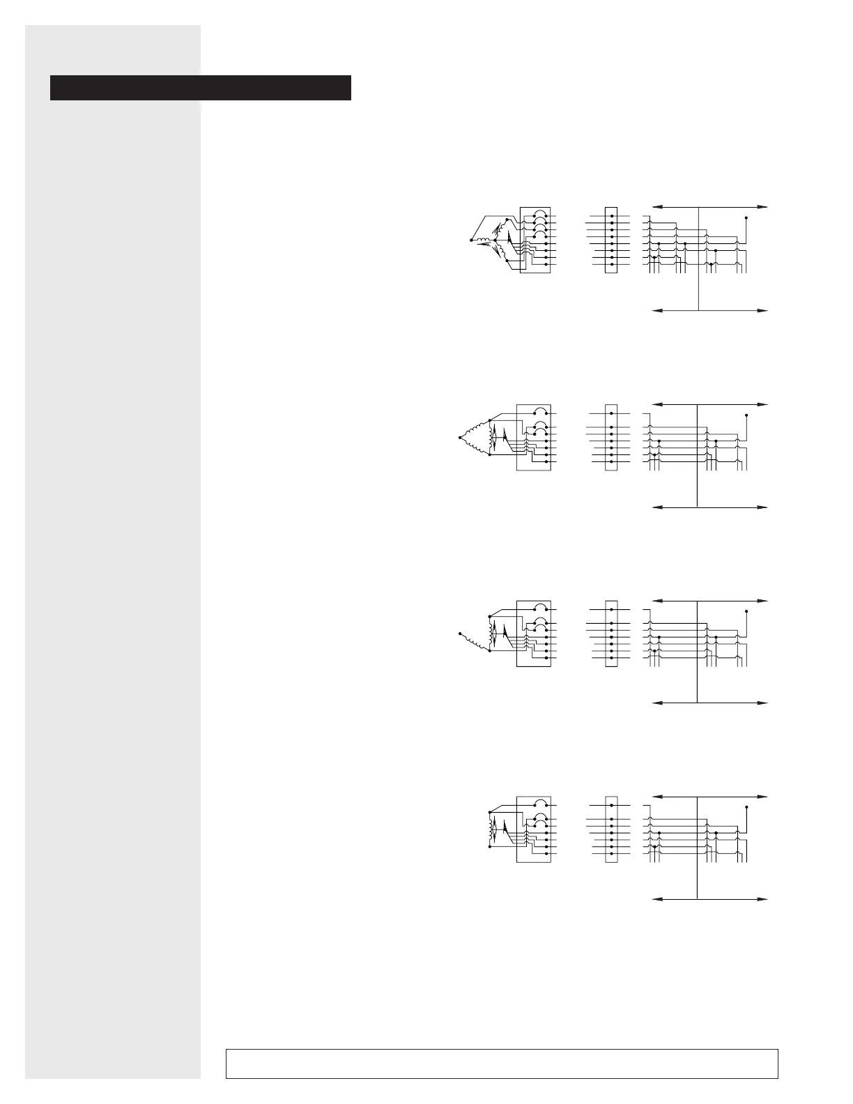
Standard
8-Wire
Schematic
2 & 2
Configuration
and 1 & 2
Configuration
2 & 2 CONFIGURATION
Receptacles 1, 2, 4, and 5
1 & 2 CONFIGURATION
Receptacles 1, 4, and 5
Note:
Receptacle number 3 can not be used
in these configurations.
The Cetra standard eight-wire
electrical system provides up to four
circuits using four hot wires, two
increased size neutrals, a system
ground and an isolated ground for
circuits four and five.
Ideally, a four-wire, WYE, 208 volt
service provides the best utilzation.
Circuits 1 & 2 can be wired for
general use. Circuits 4 & 5 can be
reserved for data and communications
requirements.
Other power supplies such as
120/240 volt delta, 120/240 volt open
delta and 120/240 volt single phase
will use circuits 1,4 and 5 with
L2 (red) circuit taped off.
Single phase 120 volt, two-wire
sytems will use L1 (black) paired
with N1 (white/black) and L4 (pink)
paired with N2 (white/red). L2 (red)
and L5 (blue) should not be used.
120/208V WYE 3 Phase 4 Wire
4 Circuit, 20 AMP, Isolated Ground
120/240V Delta Single Phase
3 Circuit, 20 AMP, Isolated Ground
120/240V Open Delta Single Phase
3 Circuit, 20 AMP, Isolated Ground
120/240V Single Phase
3 Circuit, 20 AMP, Isolated Ground
120
120
120
120
120
Building
Service
Panel
System
Power Entry
Connection
BLACK
RED
BLUE
PINK
GREEN
GRN/YLW
WH/BLK
WH/RED
L1
L2
L5
L4
G1
G2
N1
N2
BLACK
RED DO NOT USE
BLUE
PINK
GREEN
GRN/YLW
WH/BLK
WH/RED
L1
L5
L4
G1
G2
N1
N2
Designated
Utility
Designated
Computer
HNG
1
Building
Service
Panel
System
Power Entry
Connection
Designated
Utility
HNG
1
HNG
2
HNG
5
HNG
4
Designated
Computer
HNG
5
HNG
4
Dead
Metal
Dead
Metal
120
120
BLACK
RED DO NOT USE
BLUE
PINK
GREEN
GRN/YLW
WH/BLK
WH/RED
L1
L5
L4
G1
G2
N1
N2
Building
Service
Panel
System
Power Entry
Connection
Designated
Utility
HNG
1
Designated
Computer
HNG
5
HNG
4
Dead
Metal
120
120
BLACK
RED DO NOT USE
BLUE
PINK
GREEN
GRN/YLW
WH/BLK
WH/RED
L1
L5
L4
G1
G2
N1
N2
Building
Service
Panel
System
Power Entry
Connection
Designated
Utility
HNG
1
Designated
Computer
HNG
5
HNG
4
Dead
Metal
2 & 2 Configuration
1 & 2 Configuration
1 & 2 Configuration
1 & 2 Configuration
 Loading...