Do you have a question about the Kimessa CANline 02 and is the answer not in the manual?
Defines KIMESSA's liability limitations for product use, installation, and maintenance.
States that all manual information is confidential and proprietary to KIMESSA.
Highlights product focus on safety and sensor technology, requiring qualified personnel.
Details the 12-month warranty period, exclusions, and repair/replacement policies.
Provides guidelines to prevent damage during storage and transport.
Instructs on the proper disposal of the product according to EU directives.
Explains the manual's purpose for safe and proper handling of KIMESSA systems.
Outlines potential risks associated with improper use or untrained personnel.
Emphasizes regular inspections and the owner's responsibility for system safety.
Details safety precautions and regulations for using sensors in hazardous areas.
Explains the meaning of signal words like WARNING, CAUTION, and NOTE used in the manual.
Specifies required personal protective equipment for personnel working with the system.
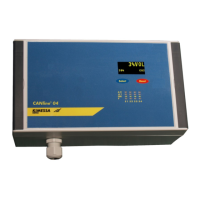
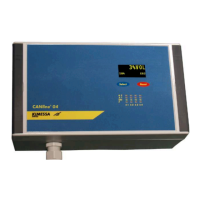
Introduces the CANline 02 gas detector control unit as a compact evaluation unit.
Specifies environmental conditions and mounting locations for the control unit.
Provides instructions for physically mounting the CANline 02 unit.
Lists the items included in the product package.
Details how to open and close the control unit housing for access.
Provides physical dimensions and installation hole specifications.
Outlines the basic steps for connecting the control unit electrically.
Explains the location and rating of fuses safeguarding relay outputs.
Describes the power supply options (230 VAC, 24 VDC) and considerations.
Recommends cable type and guidance on data transmission distance.
Details the specifications and recommended use of KIMESSA electronic cables.
Covers cable preparation, gland installation, and ATEX compliance for electrical connections.
Provides a wiring diagram for connecting analog 4..20mA detectors.
Provides a wiring diagram for connecting digital BUS detectors.
Presents a wiring schematic for standard relay contacts.
Shows the front panel layout, dimensions, and control element identification.
Explains the functions of buttons and indicators on the front panel.
Describes how to acknowledge alarms using the RESET button or remote reset.
Details the procedure to temporarily disable a single sensor.
Explains how to temporarily disable multiple sensors simultaneously.
Describes how the system displays sensor data in normal operating mode.
Guides users on navigating the system menu structure.
Details how to access and view system information and alarm history.
Indicates when the next service is due and how to reset service messages.
Shows how to view the number of programmed sensors in the system.
Explains how to check the currently loaded firmware version.
Displays the DC voltage information for the system power.
Shows the total DC current demand of the power supply.
Describes the display of maximum values for alarm overruns and sensor faults.
Explains how to manually activate and test relays.
Details how to navigate back to the main menu from other sections.
Explains how to return to the normal operating display from the menu.
Describes returning to normal operation from the main menu.
Guides on using tools to check BUS cable connections and power.
Outlines connecting the unit to a PC for startup and configuration.
Instructions for installing and starting the CANlineCMConfigurator software.
Explains how to perform a firmware update for the CANline unit.
Details the process of downloading factory settings from the monitor to the software.
Covers configuration of sensor quantity, relay quantity, and alarm texts.
Explains how to configure individual sensor parameters like mode, range, and text.
Describes alarm matrix settings, including alarm levels and delays.
Covers programming of relay functions, including buzzer and reset options.
Details how to program timer functions for relays.
Explains file operations for data transfers, such as opening, saving, and receiving.
Describes how to save and print settings as a PDF protocol.
Explains how to synchronize the CANline time with a Windows PC.
Guides on accessing sensor settings via the menu structure.
Details the password input procedure for accessing sensor settings.
Explains how to select or change the sensor number.
Describes how to set the measuring range for a sensor.
Details accessing and editing parameters for sensors 1 through 4.
Explains how to select the gas type for measurement.
Describes how to enable or disable the O2 mode for oxygen deficiency monitoring.
Provides an overview of the menu structure for configuring relays 1 through 5.
Explains the auto-reset and manual reset options for relays.
Details how to manually override relay reset functions.
Describes how to turn relays on or off in alarm conditions.
Explains the pulsating mode for relay operation during alarms.
Describes how to program the internal buzzer to sound with relay switches.
Instructions for exiting the relay configuration menu.
Introduces the menu for managing service messages.
Details how to reset the "Service Now" message and arrange maintenance.
Explains how to set the interval for the "Service Now" notification.
Instructions for returning to the main menu from service message settings.
Explains the "Service Now" display and how to reset it.
Recommends maintenance intervals and procedures for sensors and systems.
| Brand | Kimessa |
|---|---|
| Model | CANline 02 |
| Category | Security System |
| Language | English |