EasyManua.ls Logo

Kinco FV20-4T-0185G/0220L User Manual

Kinco FV20-4T-0185G/0220L
119 pages
To Next Page IconTo Next Page
Page #1 background imageLoading...
Page #1 background image
Preface
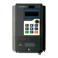
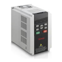
Thank you for using FV20 series Variable Frequency Drive made by Kinco Automation.
FV20 series inverter is a general-purpose high-performance vector inverter, which is mainly used to control
and adjust the speed and torque of three-phase AC asynchronous motor. It is a technical upgrade product of
FV100 series. FV20 adopts high-performance vector control technology, low speed and high torque output,
good dynamic characteristics, superior overload capability, those 45KW and below has built-in EMC filter
and brake unit, added user programmable function and background monitoring software. Support a variety of
PG cards, combined rich and powerful features, stable performance. It can be used in textile, paper, wire
drawing, machine tools, packaging, food, fans, pumps and various automated production equipment.
This manual provides information on model selection, parameters setting, trouble-shooting, and daily
maintenance. To ensure the correct installation and operation of FV20 series, please read this manual
carefully before starting the drive and keep it in a proper place and to the right person. Manufacturers should
follow the instructions in CN. and EN. version and Send it to the end-user for reference.
Precaution
To illustrate the details of the product, the illustrations in this manual are sometimes in the state of
removing the cover or safety cover. When using this product, be sure to install the cover or cover as
required and follow the instructions in the manual.
The illustrations in this manual are for illustrative purposes only and may differ from the products you
ordered.
The company is committed to continuous improvement of products, product features will be continuously
upgraded, and the information provided is subject to change without notice.
If you have any problems in use, please contact our regional agents or directly contact our customer
service center. Customer Service Phone 400-700-5281。

Table of Contents

Other manuals for Kinco FV20-4T-0185G/0220L

Questions and Answers:

Kinco FV20-4T-0185G/0220L Specifications

General IconGeneral
Power18.5kW/22kW
Rated Output Current38A/45A
Communication InterfaceRS485
Output Voltage0~Input Voltage
Control ModeVector control
Protection FeaturesOvercurrent, overvoltage, undervoltage, overheat, overload, short circuit
Cooling MethodAir cooling

Summary

Chapter 1 Safety

1.1 Safety

Details potential hazards and precautions for safe operation and handling.

1.2 Notes for Installations

Provides critical installation guidelines to prevent hazards like fire and electric shock.

Chapter 2 Product Introduction

2.3 General Specifications

Lists the key technical specifications and performance characteristics of the VFD.

Chapter 3 Installation Environment

3.1 Installation Environment Requirements

Specifies the environmental conditions necessary for proper VFD installation and operation.

Chapter 4 Wiring Guide of VFD

4.1 Wiring and Configuration of Main Circuit Terminal

Details the wiring for the main power circuit terminals of the VFD.

4.2 Wiring and Configuration of Control Circuit

Explains the wiring and configuration for the VFD's control circuit terminals.

Chapter 5 Operation Instructions of Kinco VFD

5.1 Using Operation Panel

Describes the appearance, keys, and display functions of the VFD operation panel.

5.2 Operation Mode of VFD

Explains the different control, running, and operating modes of the VFD.

5.3 Power on the Drive for the First Time

Provides step-by-step instructions for the initial power-up and startup of the VFD.

Chapter 6 Parameter Introductions

6.1 Group A0: Basic Operating Parameters

Details parameters related to user password, control mode, and frequency selection.

6.6 Group A5: Control Parameters

Details parameters for speed and torque control, including PID tuning.

6.7 Group A6: Control Terminals Parameters

Describes the configuration and functions of the VFD's multi-function input/output terminals.

6.9 Group A8: Fault Parameters

Details parameters for protective actions, fault masking, and overload settings.

6.10 Group b0: Motor Parameters

Explains parameters required for matching the VFD to the motor's characteristics.

6.11 Group b1: V/F Parameters

Details parameters for setting V/F curves to optimize performance for different loads.

6.12 Group b2: Enhanced Parameters

Covers advanced parameters for carrier wave, voltage, and current limiting.

6.14 Group b4: Keyboard Parameters

Explains parameters for controlling operation panel lock and key functions.

6.16 Group C1: Process PID Parameters

Details parameters for configuring PID control loops for process automation.

Chapter 7 Troubleshooting

Chapter 9 List of Parameters

C2: Simple PLC

Describes parameters for the integrated Simple PLC function.

Group d1: Fault Record

Details parameters for storing and retrieving fault history information.

Chapter 11 Basic Adjustment Guide

11.1 Motor Parameter Self-Tuning

Guides through the process of automatically tuning motor parameters for optimal performance.

Related product manuals