ADJUSTMENTS
ADJUSTING FENCE 90 DEGREES TO BLADE
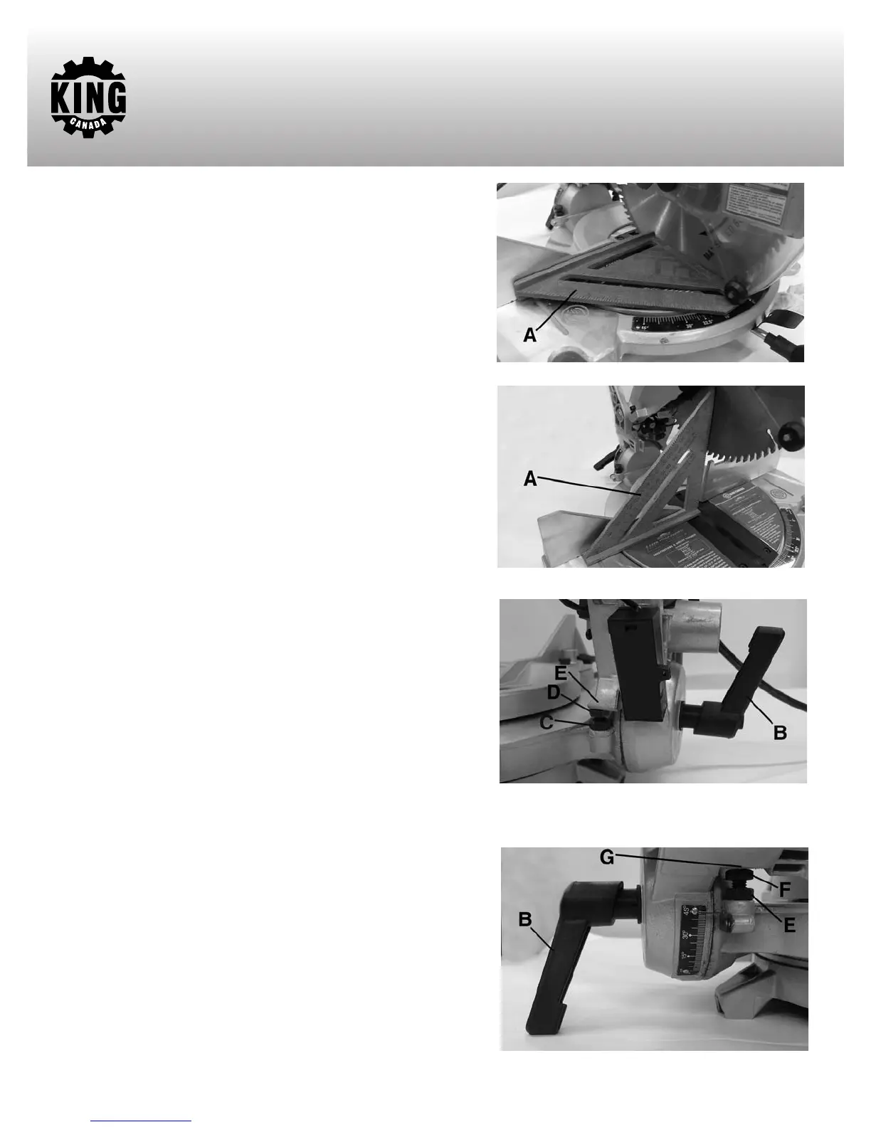
1. DISCONNECT THE SAW FROM THE POWER SOURCE.
2. Place the cutting arm in the 90 degree straight cut-off position, as
shown in Fig. 11, and tighten the table lock knob.
3. Using a square (A) Fig. 11, place one end of the square against the
blade and the other end against the fence, as shown.
4. Check to see if the fence is 90 degrees to the blade.
5. If an adjustment is necessary, loosen the four hex. bolts found at the
rear of the fence and adjust until it is 90 degrees to the blade. Then
retighten all hex. bolts.
ADJUSTING 90 AND 45 DEGREE BEVEL STOPS
These positive stops enable you to rapidly position the blade at the 90
degree and 45 degree bevel positions.
1.
DISCONNECT THE SAW FROM THE POWER SOURCE.
2. Adjust the cutting arm so that the blade is at 90 degrees to the table, as
shown in Fig. 12, and tighten the bevel lock handle.
3. Using a square (A) Fig. 12, place one end of the square on the table
and the other end against the blade. Check to see if the blade is at 90
degrees to the table.
4. If an adjustment is necessary, loosen bevel lock handle (B) Fig. 13, and
tilt cutting arm until the blade is 90 degrees to the table. NOTE: It may
be necessary to loosen locknut (C) and bolt (D) to accomplish this.
Adjust bolt (D) height until it comes in contact with head (E). Retighten
hex. nut (C).
5. A bevel angle pointer adjustment may be needed, loosen pointer screw
and position pointer to the 0 mark.
6. Tilt the cutting arm all the way to the left position and tighten the bevel
lock handle.
7. Using a combination square, check to see if the blade is 45 degrees to
the table.
8. If an adjustment is necessary, loosen bevel lock handle (B) Fig. 14, and
tilt the cutting arm until the blade is 45 degrees to the table. NOTE: It
may be necessary to loosen locknut (E) and hex. bolt (F) to accomplish
this. Adjust hex. bolt (F) height until it comes in contact with head (G).
Retighten hex. nut (E).
FIGURE 11
FIGURE 12
FIGURE 13
FIGURE 14