4
EN
4
3
2
6
5
6
5
2 x 1
8
9
7
10
11
4 x 1
6
5
1
6
5
12
3 x 1,5
85 GR + 5,1 x 2
2
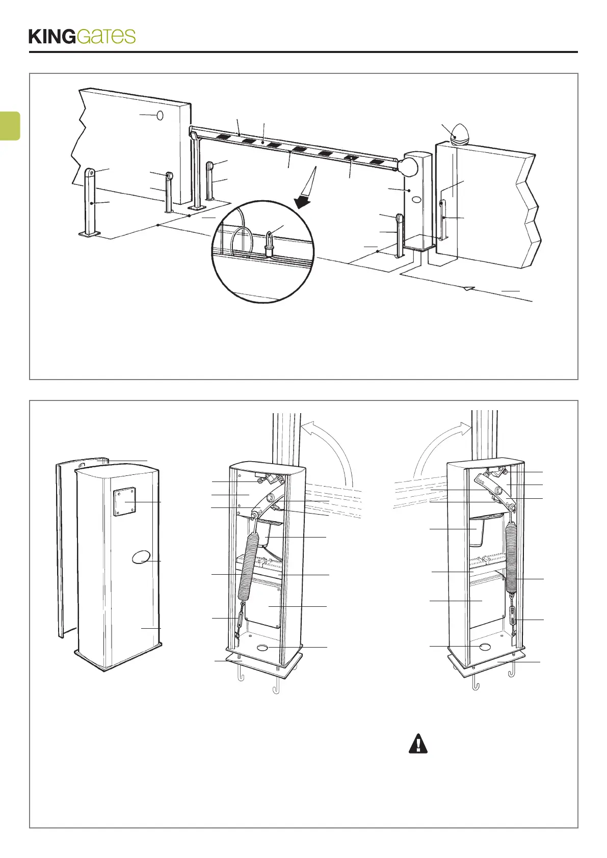
1 OPEN 4000
2 Column for the key selector
3 Key selector
4 Digital keypad
5 Column for the photocell
6 Photocell
7 Pneumatic edge or red rubber
8 Protectiveredrubberprole
9 Aluminium bar
10 Flashing lights
11 Redreectorstrips
12 Flashing light
16
3
2
1
3
WIL -sx-
4
11
12
13
9
14
15
5
6
7
8
10
WIL -dx-
11
12
13
9
14
15
10
8
7
6
5
4
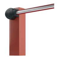
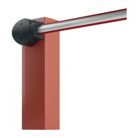
1 Cubicle
2 Unlock device
3 Barconnectingange
4 Shock absorber with safety stop
5 Gearmotor
6 Gearmotor external lever
7 Balancing spring
8 Spring adjustment tie-rod
9 Housing for 2 batteries, 12 V - 6 Ah
10 Anchoragebasewithsh-tailclamps
11 Eccentrics for adjusting the slowing down point
12 Slowing down limit switch
13 24 V motor
14 Control unit
15 Cable input hole
16 Cover
CAUTION! - The key to the cover
is ONLY for the operator and is diffe-
rent from the one for unlocking which
is for the USER. The USER must not
access the adjustment devices or
control panel.